
PipeWithHotwell
Created Wednesday 10 October 2012
This model defines the basic geometric parameters of a tube bundle with a tube bundle.
1. Purpose of Model
This model gives a description of the geometric properties of a pipe bundle. This geometry definition is used by L3 control volumes. The idea is to provide a simple way to calculate the filling level within heat exchangers with condensing steam at the tube side.
2. Physical Insight
The volume and heat transfer area of the pipe bundle are calculated according to the properties shown in the next list:
- Diameter of the component
- Length of the component (one pass)
- Number of tubes in parallel
- Number of passes of the internal tubes
- height, width and length of the attached hotwell
3. Limits of Validity
Lengths and diameters of the passes should be greater than zero.
4. Nomenclature
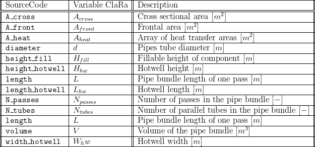
5. Governing Equations
5.1 System Description and General model approach
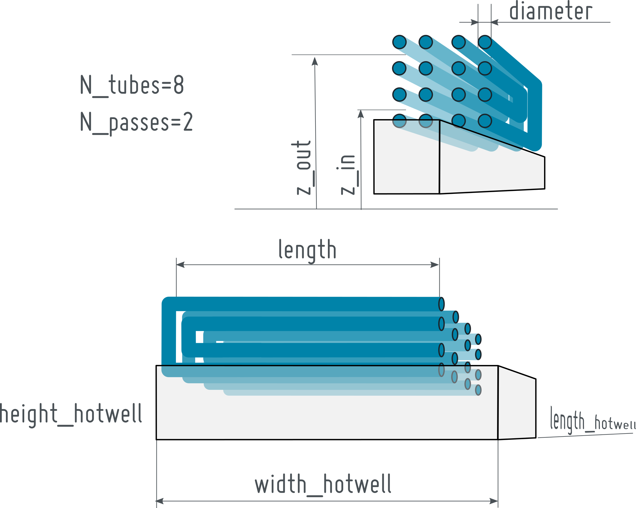
The model defines the geometrical elements needed in control volume models of the level of detail L2/L3 with the shape of a tube or a tube bundle with an attached block-shaped hotwell.
The general pipe geometry is displayed in the figure below with its most relevant parameters.
5.2 Governing Model Equations
The volume and areas in Eq. (1) to (3) consider the standard formulas for volumes and areas of cylindrical geometries together with the number of parallel tubes  in the stack and the number of passes per pipe
  as shown in the figure above.
The volume  is calculated by relation in Eq.1

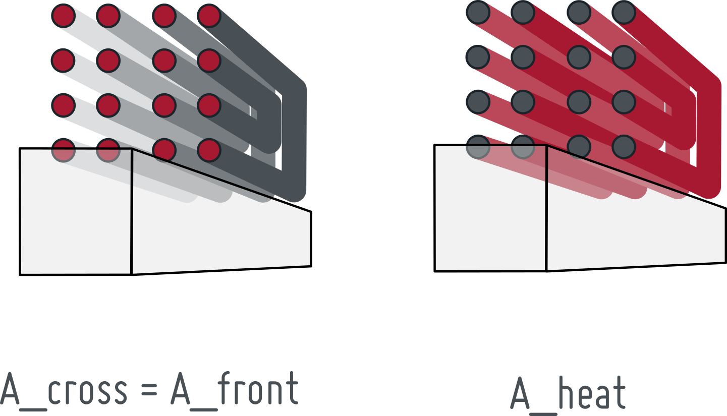
The frontal area is determined by Eq. 2.
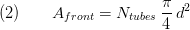
The cross sectional area is equivalent to the frontal area.

The basic idea is to separate heat transfer and mass storage in the applying component. Thus the filling level takes only the hotwell into account and the nominal horizontal area is therefore
 .
.
The vector of the heat transferring area  has the length
  . Thus, the only entry is the lateral surface of the pipe bundles computed by Eq. 5. Note that the hotwell's surrounding faces are not considered in the heat transfer area

As mentioned above only the hotwell is considered in the liquid accumulation. Thus, the fillable height of the component is
6. Remarks for Usage
Whenever the block's volume or its cross section is zero or negative an assert will raise an error message.
- A_cross > 0
- volume > 0
8. Validation
9. References
10. Authorship and Copyright Statement for original (initial) Contribution
Author:
DYNCAP/DYNSTART development team, Copyright 2011 - 2025.
Remarks:
This component was developed during DYNCAP/DYNSTART projects.
Acknowledgements:
ClaRa originated from the collaborative research projects DYNCAP and DYNSTART. Both research projects were supported by the German Federal Ministry for Economic Affairs and Energy (FKZ 03ET2009 and FKZ 03ET7060).
CLA:
The author(s) have agreed to ClaRa CLA, version 1.0. See https://claralib.com/pdf/CLA.pdf
By agreeing to ClaRa CLA, version 1.0 the author has granted the ClaRa development team a permanent right to use and modify his initial contribution as well as to publish it or its modified versions under the 3-clause BSD License.
11. Version History
20.02.2012 - v01 - Initial implementation - Friedrich Gottelt, XRG Simulation GmbH