
HollowCylinderWithTubes
Created Tuesday 08 April 2014
This model defines the basic geometric parameters of a hollow cylinder with tubes.
1. Purpose of Model
The model is used to define the geometry of a cylindrical control volume (of the level of detail L2) with a tube bundle in it for heat transfer.
2. Physical Insight
The volume and heat transfer area of the pipe bundle are calculated according to the properties shown in the next list:
- Diameter of the internal tubes
- Length of the internal tubes (one pass)
- Number of internal tubes in parallel
- Number of passes of the internal tubes
- Cylinder dimensions (Length, diameter)
- Orientation and flow orientation of the cylinder
3. Limits of Validity
Lengths and diameters of the passes should be greater than zero.
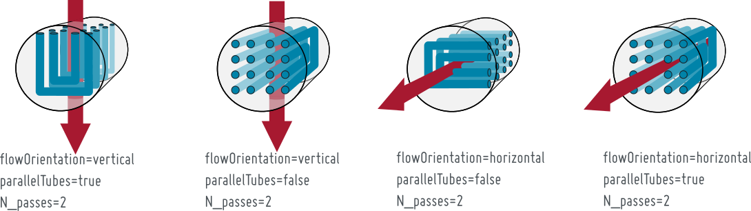
4. Nomenclature
5. Governing Equations
5.1 System Description and General Model Approach
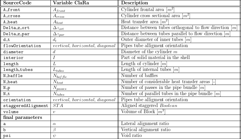
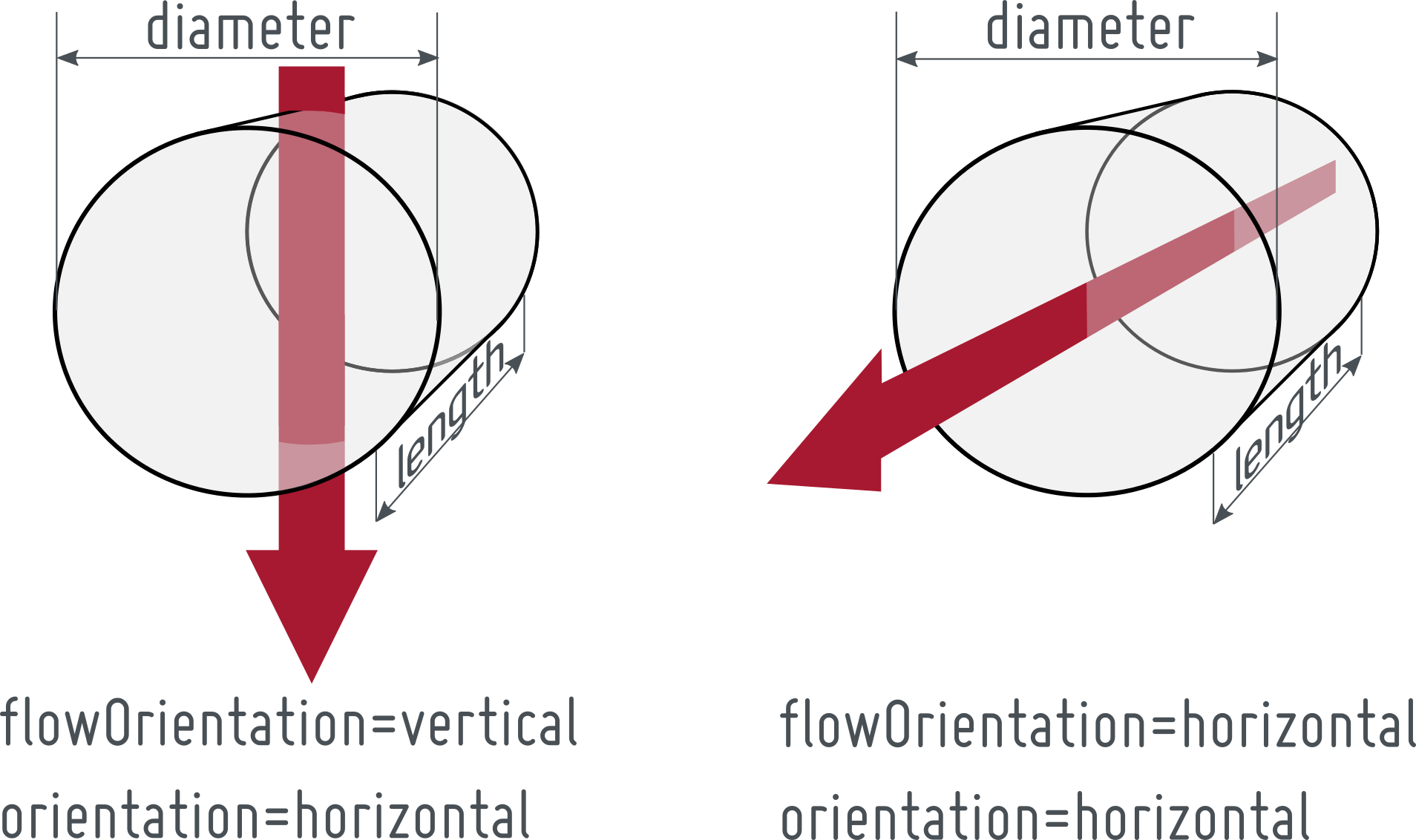
This model defines geometrical properties of a cylinder with a tube bank inside. The orientation of the cylinder can be set to "horizontal" or to "vertical" as can be seen in the following pictures. The model defines also the flowOrientation through the component.
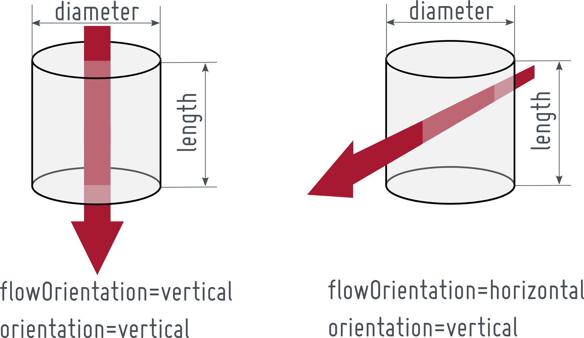
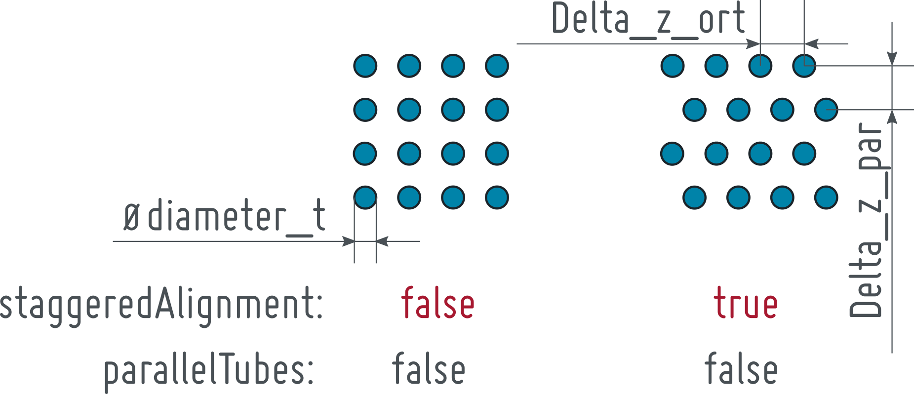
The orientation of the tube bank inside the cylinder is defined with respect to the flowOrientation applying the Boolean parameter parallelTubes. This is illustrated below:
The same holds for a vertical orientation of the component.
Basically, the HollowCylinderWithTubes geometry is characterised by the cylinder dimensions (length, diameter, orientation), the shell side flow orientation and the tube bundle dimensions (diameter, length, number of tubes and passes) with its relative orientation to the shell side flow direction (parallelTubes).
5.2 Governing Model Equations
The volume of the element is given by Eq.1.

Depending on the shell side flow direction is the frontal area, determined by Eq.2.
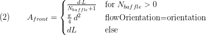
The calculation for the frontal area with  is taken from [1] and is used for calculation of the heat transfer coefficient for one phase flow in tube bundle heat exchangers. For other cases this parameter should be set to zero.
The cross sectional area arises from Eq.3 according to the relative orientation of the tubes.
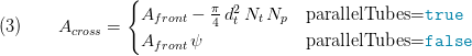
with  as void ratio (see Eq. 9). The
  for parallelTubes=false is used for calculation of heat transfer coefficients for one phase flow according to [2].
The nominal horizontal area is calculated via Eq. 4:
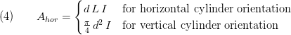
with  as part of the solid material of the shell (see Eq.7)
The entries of the vector of the heat transfer area  have to be determined depending on the relative orientation of the tube bundle. For the HollowCylinderWithTubes geometry the heat transfer area array is of the length
  .
.
The first entry is the surface for the calculation of the external area of the cylinder (see Eq. 5.1)
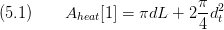
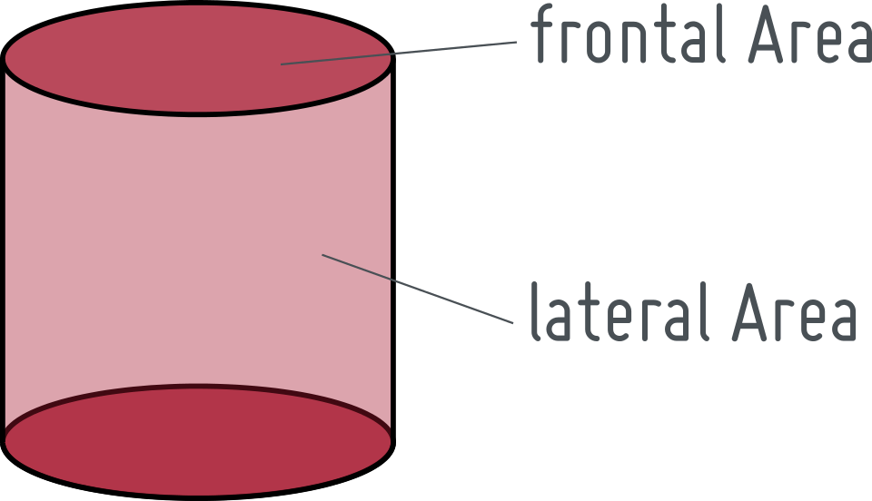
The overall lateral surface of the internal tubes is calculated by the relation in Eq.5.2 and is stored as the second entry of  .
.

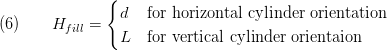
The fillable height of the component is according to the cylinder orientation set to
The material content of the block is given by
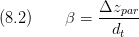
The lateral and vertical alignment ratio are given by
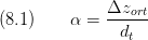
and,
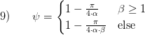
Finally the void ratio is,
6. Remarks for Usage
Whenever the tubes' volume exceeds the cylinder's volume due to a high number of tubes or a large number of passes an assert will raise and error message. The same holds if the cross sectional area A_cross vanishes due to a too high interior. Additionally, z_in and z_out must be smaller than height_fill and greater equal than 0.
- A_cross > 0
- volume > 0
- z_in < height_fill
- z_out < height_fill
- z_in >= 0
- z_out >= 0
7. Validation
8. References
[1] VDI Wärmeatlas (VDI Heat Atlas), Chapter Gh, 9th edition 2002
[2] VDI Wärmeatlas (VDI Heat Atlas), Chapter Gg, 9th edition 2002
9. Version History
20.02.2012 - v01 - Initial implementation - Friedrich Gottelt, XRG Simulation GmbH
08.02.2016 - v1.1.0 - bugfixed A_front (for flow orientation not equal orientation)