
HollowBlockWithTubesAndCarrierTubes
Created Tuesday 08 April 2014
This model defines the basic geometric parameters of a hollow block with tubes assembled to a set of carrier tubes.
1. Purpose of Model
The model is used to define the geometry of a block-shaped control volume (of the level of detail L2) with a tube bundle in it for heat transfer. The tube bundle is assembled to so-called carrier tubes.
2. Physical Insight
The volume and heat transfer areas are calculated according to the following properties:
- Block dimensions (Length, Height, Width)
- Tube dimensions (Diameter, Length (one pass))
- Number of tubes in parallel
- Number of passes of the internal tubes
- Flow orientation of the shell side flow
- Orientation of the tubes
- Number and diameter of the carrier tubes
3. Limits of Validity
Lengths and diameters of the passes should be greater than zero.
4. Nomenclature
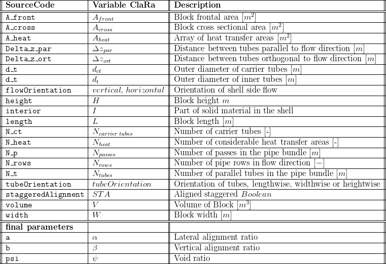
5. Governing Equations
5.1 System Description and General Model Approach
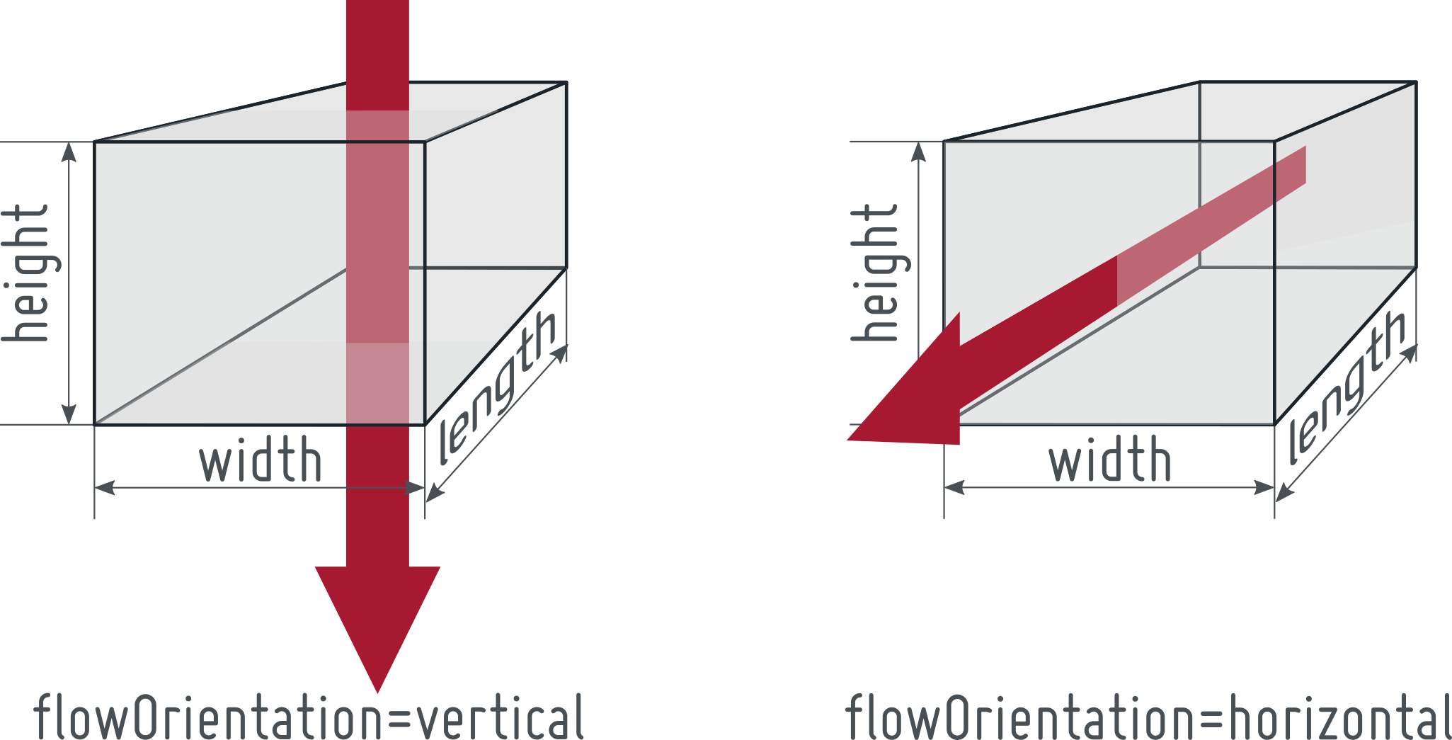
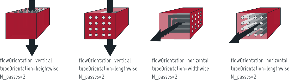
This model defines geometrical properties of a block shaped shell with a tube bank inside. The orientation of the block and the understanding of its main dimensions is always the same, as illustrated below. Furthermore, there is an orientation of the shell flow defined via flowOrientation. This parameter can be one of "vertical" and "horizontal".
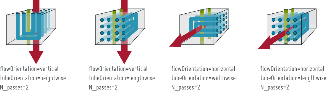
The orientation of the tube bank inside the block is defined with the parameter tubeOrientation. This is illustrated below:
The HollowBlockWithTubes geometry is basically characterized by the block dimensions (length, height, width), the shell side flow orientation and the tube bundle dimensions (diameter, length, number of tubes and passes) with its relative orientation to the shell side flow direction. For the sake of simplicity, the tubes' volume is characterized by the the block's outer dimensions length, height and width, respectively. This idea takes the flowOrientation as well as the orientation of the tube bank into account and will be applied for all derived parameters in this geometry definition. The length of the carrier tubes equals the height of the volume.
5.2 Governing Model Equations
The HollowBlockWithTubesAndCarrierTubes geometry is basically characterized by the block dimensions (length, height, width), the shell side flow orientation, the tube bundle dimensions (diameter, length, number of tubes and passes) with its relative orientation to the shell side flow direction and the diameter and number of the carrier tubes.
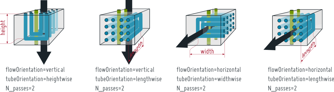
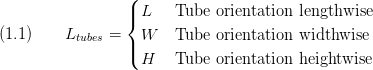
The tube length is defined with the parameter tubeOrientation.
The volume of the element is given by Eq.1.2,

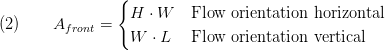
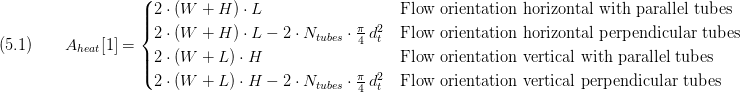
Also depending on the shell side flow direction the frontal area is determined by Eq.2.
The cross sectional area arises from Eq.3 according to the relative orientation of the tubes.
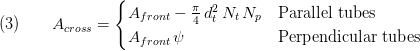
with  as void ration (see Eq. 9).
The nominal horizontal area is calculated via Eq. 4:
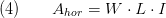
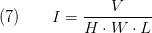
with I as part of the solid material of the shell (see Eq.7)
The entries of the vector of the heat transfer area  also has to be determined depending on the shell side flow orientation and the relative orientation of the tube bundle. For the HollowBlockWithTubesAndCarrierTubes geometry the heat transfer area array is of the length
  .
.
The first entry of  is the lateral surface of the block (see Eq. 5.1)
The overall lateral surface of the internal tubes is calculated by the relations in Eq.5.2 and is stored as the second entry of .

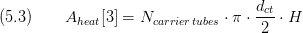
The surface of the carrier tubes on the inner face of the block is set as third entry of the vector (see Eq.5.3)
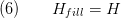
The fillable height of the component is equivalent to the height of the block
The material content of the block is given by the interior parameter in Eq.7
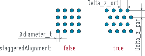
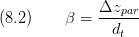
The lateral and vertical alignment ratio are given by
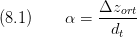
and,
Finally the void ratio is determined via
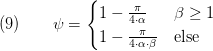
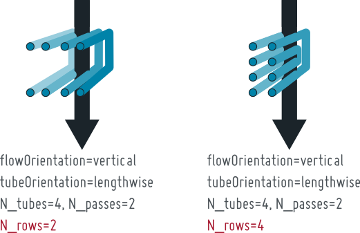
For some advanced heat transfer models the number of rows passed in shell side flow direction may be of interest. This is defined by N_rows as defined below:
6. Remarks for Usage
Whenever the tubes' volume exceeds the block's volume due to a high number of tubes or a large number of passes an assert will raise an error message. The same holds if the cross sectional area A_cross vanishes due to a too high interior. Additionally, z_in and z_out must be smaller than height_fill and greater equal than 0. Also a tube bundle parametrized too large for the volume will lead to an error message.
- A_cross > 0
- volume > 0
- z_in < height_fill
- z_out < height_fill
- z_in >= 0
- z_out >= 0
- Delta_l_par < 0
- Delta_l_ort < 0
- A_narrowed_par < 0
- A_narrowed_ort < 0
If one or more of the parameters Delta_l_par, Delta_l_ort, A_narrowed_par or A_narrowed_ort are below 0 the tube bundle is too large in one or multiple volume dimensions. Please check the tube spacing or the number of tube rows to reduce tube bundle size in the specified dimension or increase the height, width or length of the volume so that the tube bundle fits inside.
If the tube orientation is parallel to flow direction, please be aware that the parameters Delta_z_par and Delta_z_ort have no reasonable meaning geometrically but maybe have an impact in the heat transfer corellation for tube bundles.
7. Validation
8. References
9. Version History
20.02.2012 - v01 - Initial implementation - Friedrich Gottelt, XRG Simulation GmbH
08.02.2016 - v1.1.0 - bugfixed Volume calculation - Timm Hoppe, XRG Simulation GmbH
07.03.2019 - v1.4.0 - parameter tubeOrientation introduced to improve flexibility of parametrisation