VolumeVLE L2
Created Monday 22 October 2012
Basic finite volume model taking heat and mass storage as well as convective heat transfer and pressure differences due to friction and geostatic effects into account.
1. Purpose of Model
The model is recommended when the media properties like enthalpy and especially density can be assumed to be homogeneously distributed. This is especially the case in adiabatic pipes and moderately heated/cooled liquid pipes. The model is used as a basic model to form various components like:
- Compact heat exchangers.
2. Level of Detail, Physical Effects Considered and Physical Insight
2.1 Level of Detail
Referring to Brunnemann et al. [1], this model refers to the level of detail L2 because the system is modelled with the use of balance equations for one distinct zone, namely the whole fluid volume enclosed by surrounding walls.
2.2 Physical Effects Considered
- Conservation of mass
- Simplified conservation of momentum (no advection term, steady state)
- Conservation of energy
- Reverse flow
- Heat Transport due to convection
- Pressure loss due to friction.
- Ideal phase separation or ideal mixing based on phenomenological model ideas
2.3 Level of Insight
Heat Transfer
- ControlVolumes:Fundamentals:HeatTransport:Generic HT:Adiabat L2
- ControlVolumes:Fundamentals:HeatTransport:Generic HT:IdealHeatTransfer L2
- ControlVolumes:Fundamentals:HeatTransport:Generic HT:Constant L2
- ControlVolumes:Fundamentals:HeatTransport:Generic HT:CharLine L2
- ControlVolumes:Fundamentals:HeatTransport:VLE HT:NusseltPipe1ph L2
- ControlVolumes:Fundamentals:HeatTransport:VLE HT:NusseltPipe2ph L2
- ControlVolumes:Fundamentals:HeatTransport:VLE HT:NusseltShell1ph L2
- ControlVolumes:Fundamentals:HeatTransport:VLE HT:NusseltShell2ph L2
Pressure Loss
- ControlVolumes:Fundamentals:PressureLoss:Generic PL:NoFriction L2
- ControlVolumes:Fundamentals:PressureLoss:Generic PL:LinearPressureLoss L2
- ControlVolumes:Fundamentals:PressureLoss:Generic PL:QuadraticNominalPoint L2
- ControlVolumes:Fundamentals:PressureLoss:VLE PL:PressureLossCoefficient L2
- ControlVolumes:Fundamentals:PressureLoss:VLE PL:QuadraticNominalPoint L2
Spacial Distribution Aspects
- ControlVolumes:Fundamentals:SpatialDistributionAspects:IdeallyStirred
- ControlVolumes:Fundamentals:SpatialDistributionAspects:IdeallySeparated
3. Limits of Validity
- Fixed control volume.
- Averaging assumption violated, e.g. phase change in volume. This will result in imprecise transients.
- The equations imply that the outlet states are equal to the states in the balance equations - Not true for large volumes and high gradients.
4. Interfaces
4.1 Physical Connectors
Basics:Interfaces:FluidPortIn inleti "nlet port"
Basics:Interfaces:FluidPortOut outlet "outlet ports"
Basics:Interfaces:HeatPort a heat
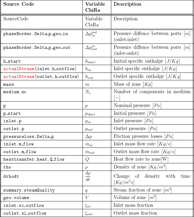
5. Nomenclature

6. Governing Equations
6.1 System Description and General model approach
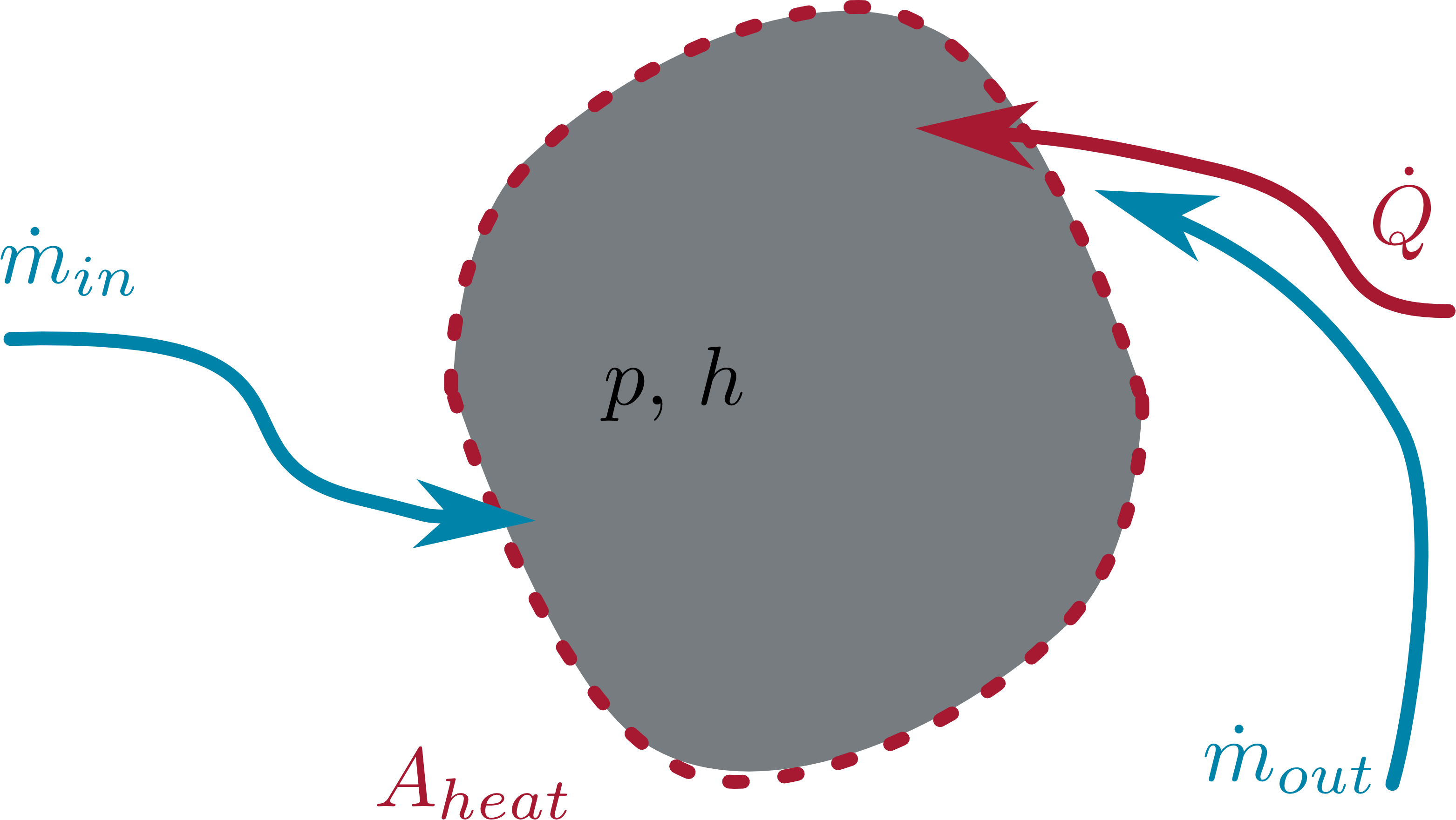
The general model structure is defined as illustrated below: One constant (i.e. fixed size) control volume is considered. Heat can be transferred from the surrounding, depending on the temperature difference. This effect is handled by the model's replaceable model for the heat transfer, see section 2.3 Heat Transfer. Furthermore, losses to friction are considered which is also handled by replaceable models, see section 2.3 Pressure Loss.

6.2 Governing Model Equations
Conservation of Mass
The mass balance for the constant volume considers mass flows through the inlet and outlet connectors. The balance equation reads:

Conservation of Momentum
We use balance of stationary momentum to model the pressure losses on the control volume.
Firstly, two sources of pressure losses are considered:
- Difference on the heights of the ports.
- Friction inside the control volume.
In the model the pressure distribution is given by the difference in the heights of the ports (z coordinate) and the influence of friction in the flow direction, which is given with the direction of the flow; for example if the outlet port is higher and the flow is "in to out". Friction is directed in opposite flow direction, i.e. is positive under design flow conditions and negative otherwise.
Conservation of Energy
The energy balance for the control volume considers incoming and outgoing enthalpy flow rates as well as heat transport into the system. Please note, there are two terms in the equation below that take the derivatives of density and pressure into account. These terms are derived from the total derivative of the inner energy of the zone and appear here due to the special choice of state variables as discussed in Basic Concepts of Modelling.

The heat flow rate to the surrounding is determined by applying a replaceable heat transfer model, see section 2.3 Heat Transfer.
The model's density is taken as an explicit function of the states, its total derivative should be used for completeness of the model given by:

Chemistry
no chemistry is considered:

Summary
A summary is available including the following:
- an outline record:

- Basics:Records:FlangeVLE inlet, outlet
- Basics:Records:FluidVLE L34 fluid
7. Remarks for Usage
This model is applied in a number of component models either via instantiation or inheritance, see for example Components:HeatExchangers:HEXvle2vle L3 2ph CU ntu
9. References
[1] Johannes Brunnemann and Friedrich Gottelt, Kai Wellner, Ala Renz, André Thüring, Volker Röder, Christoph Hasenbein, Christian Schulze, Gerhard Schmitz, Jörg Eiden: "Status of ClaRaCCS: Modelling and Simulation of Coal-Fired Power Plants with CO2 capture", 9th Modelica Conference, Munich, Germany, 2012
10. Authorship and Copyright Statement for original (initial) Contribution
Author:
DYNCAP/DYNSTART development team, Copyright 2011 - 2022.
Remarks:
This component was developed during DYNCAP/DYNSTART projects.
Acknowledgements:
ClaRa originated from the collaborative research projects DYNCAP and DYNSTART. Both research projects were supported by the German Federal Ministry for Economic Affairs and Energy (FKZ 03ET2009 and FKZ 03ET7060).
CLA:
The author(s) have agreed to ClaRa CLA, version 1.0. See https://claralib.com/pdf/CLA.pdf
By agreeing to ClaRa CLA, version 1.0 the author has granted the ClaRa development team a permanent right to use and modify his initial contribution as well as to publish it or its modified versions under the 3-clause BSD License.
11. Version History
Date - Version - Description of changes - author/revisor
25.06.2013 - v0.1 - initial implementation of the model - Friedrich Gottelt, XRG Simulation
25.06.2014 - v0.2 - application of the internal communication concept (iCom) - Friedrich Gottelt, XRG Simulation
24.04.2017 - v1.2.2 - added noEvent Operator to actualStream - Timm Hoppe, XRG Simulation
08.08.2017 - v1.2.3 - added noEvent Operator to actualStream - Timm Hoppe, XRG Simulation
Backlinks: ClaRa:Components:HeatExchangers:HEXvle2gas L3 1ph BU ntu ClaRa:Components:HeatExchangers:HEXvle2gas L3 1ph BU simple ClaRa:Components:HeatExchangers:HEXvle2vle L3 1ph BU ntu ClaRa:Components:HeatExchangers:HEXvle2vle L3 1ph BU simple ClaRa:Components:HeatExchangers:HEXvle2vle L3 1ph kA ClaRa:Components:HeatExchangers:HEXvle2vle L3 2ph BU ntu ClaRa:Components:HeatExchangers:HEXvle2vle L3 2ph BU simple ClaRa:Components:HeatExchangers:HEXvle2vle L3 2ph CH ntu ClaRa:Components:HeatExchangers:HEXvle2vle L3 2ph CH simple ClaRa:Components:HeatExchangers:HEXvle2vle L3 2ph CU ntu ClaRa:Components:HeatExchangers:HEXvle2vle L3 2ph CU simple ClaRa:Components:HeatExchangers:IdealShell L2 ClaRa:Components:HeatExchangers:PlateHEXvle2vle L3 2ph ntu ClaRa:Components:HeatExchangers:TubeBundle L2 ClaRa:Components:MechanicalSeparation:FeedWaterTank L2 ClaRa:Components:Sensors:SensorVLE L3 T ClaRa:Components:VolumesValvesFittings:Fittings:SprayInjectorVLE L3 ClaRa:Basics:ControlVolumes:Fundamentals:SpatialDistributionAspects:IdeallySeparated
