
FlameRoom1
Created Samstag 01 Juli 2017
Stationary model of a flame room computing the values for outlet enthalpies, temperatures, mass flow rates and pressure for vle and flue gas media from given values.
1. Purpose of Model
The model is supposed to be used for the simplified simulation of static cases. Its main purpose is to provide appropriate start or nominal values for similar dynamic model versions.
2. Level of Detail, Physical Effects Considered and Physical Insight
2.1 Level of Detail
Referring to Brunnemann et al. [1], this model refers to the level of detail L1 because the model only computes a set of parameters under specific conditions i.e. stationary.
2.2 Physical Effects Considered
- Evaporation of fluid at constant pressure
- Gravimetric pressure losses
3. Limits of Validity
The model is only able to calculate stationary situations.
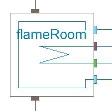
4. Interfaces
4.1 Steam Signals
For details see SteamSignal_blue, SteamSignal_red and SteamSignal_green.
Flue gas inlet: Grey connector
Flue gas outlet: Grey connector
Wall inlet: Blue connector
Wall outlet: Blue connector
Bundle inlet: Red connector
Bundle outlet: Green connector
4.2 Medium Models
VLE medium model
Flue gas medium model
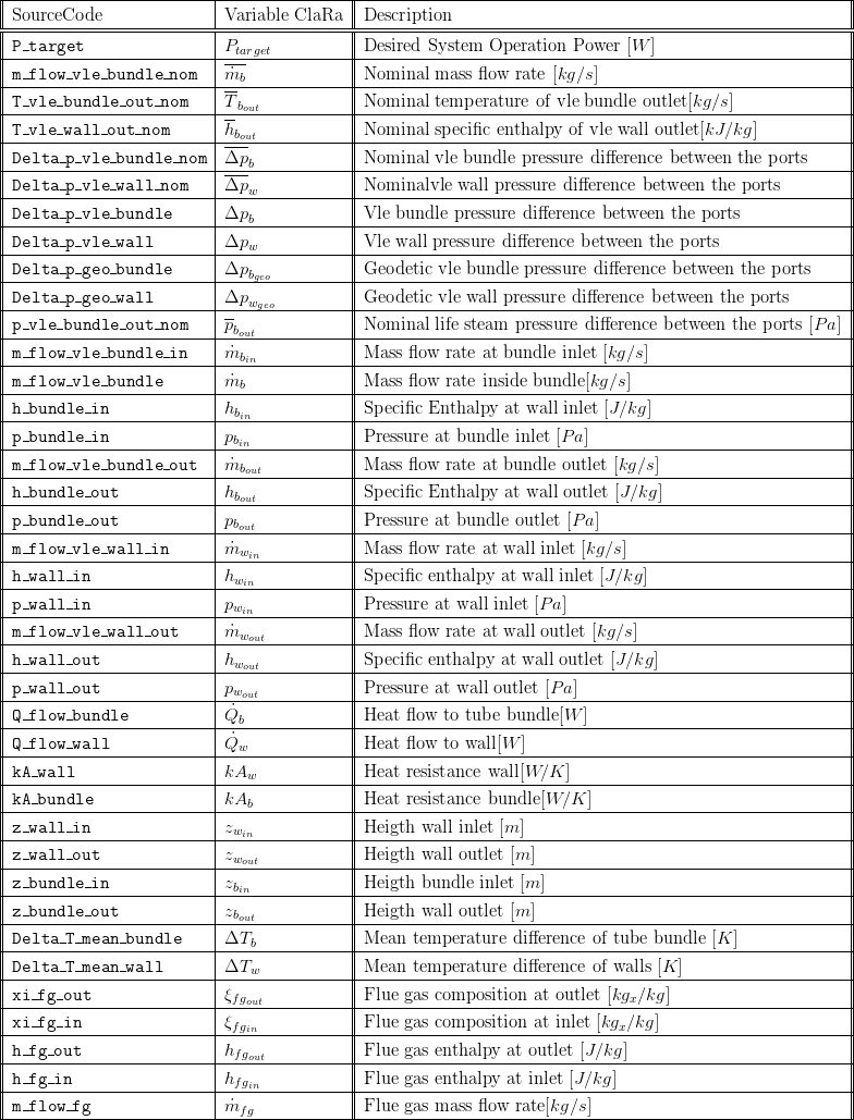
5. Nomenclature
6. Governing Equations
In general the derived equations for the model consider stationary balance of energy.
6.1 Governing Model Equations
The signal directions at the connectors of the flame room are illustrated below:
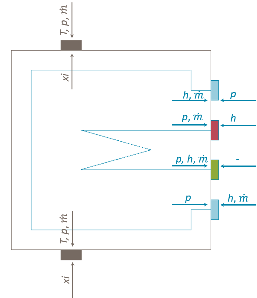
The relevant equations for the unknown connector parameters are listed below. All other connector parameters are given via the parameter dialogue of the component or from neighbouring components.
The heat flows to bundle and wall are calculated as follows:


The bundle mass flow rate is is set by the user via a parameter. P_target_ is used to calculate the part load mass flow rate.

The friction pressure losses are set by the user via parameters. A load dependent table is used to calculate the part load pressure drops.


The geodetic pressure losses are calculated using the component inlet and outlet heights.


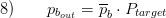
The bundle outlet pressure is set by the user via a parameter. P_target_ is used to calculate the part load mass flow rate.
The bundle and wall inlet pressure is calculated with the pressure differences due to friction and geodetic height.


The inlet temperature of the flue gas is calculated within a media object using the calculated inlet enthalpy.

The flue gas mass flow and composition remain constant.
7. Remarks for Usage
The model can only be connected with components with matching connector colour (see Example of Usage in StaticCycles).
9. References
[1] Johannes Brunnemann and Friedrich Gottelt, Kai Wellner, Ala Renz, André Thüring, Volker Röder, Christoph Hasenbein, Christian Schulze, Gerhard Schmitz, Jörg Eiden: "Status of ClaRaCCS: Modelling and Simulationof Coal-Fired Power Plants with CO2 capture", 9th Modelica Conference, Munich, Germany, 2012
10. Authorship and Copyright Statement for original (initial) Contribution
Author:
DYNCAP/DYNSTART development team, Copyright 2011 - 2025.
Remarks:
This component was developed during DYNCAP/DYNSTART projects.
Acknowledgements:
ClaRa originated from the collaborative research projects DYNCAP and DYNSTART. Both research projects were supported by the German Federal Ministry for Economic Affairs and Energy (FKZ 03ET2009 and FKZ 03ET7060).
CLA:
The author(s) have agreed to ClaRa CLA, version 1.0. See https://claralib.com/pdf/CLA.pdf
By agreeing to ClaRa CLA, version 1.0 the author has granted the ClaRa development team a permanent right to use and modify his initial contribution as well as to publish it or its modified versions under the 3-clause BSD License.
11. Version History
04.05.2016 - Version 1.1.1 - Friedrich Gottelt, XRG Simulation GmbH
06.06.2017 - Version 1.2.2 - Added summary, Timm Hoppe XRG Simulation GmbH