
Boiler simple
Created Monday 04 August 2014
Stationary model of a boiler with feedwater heating and reheating part.
1. Purpose of Model
The model is supposed to be used for the simplified simulation of static cases. Its main purpose is to provide appropriate start or nominal values for similar dynamic model versions.
It computes the stationary values of:
- Heat release in live steam at current load.
- Heat release in reheated steam at current load.
- Inlet pressure.
- Live steam pressure at current load.
- Reheated steam pressure at current load
2. Level of Detail, Physical Effects Considered and Physical Insight
2.1 Level of Detail
Referring to Brunnemann et al. [1], this model refers to the level of detail L1 because the model only computes a set of parameters for the given scenario and from the characteristic line of pressure.
2.2 Physical Effects Considered
- Conservation of Energy
- Pressure drop calculation via characteristic lines
3. Limits of Validity
The model is only able to calculate stationary situations.
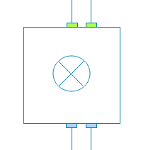
4. Interfaces
4.1 Steam Signals
For details see SteamSignal_blue, SteamSignal_red and SteamSignal_green .
Feedwater inlet: Blue connector
Steam outlet: Green connector
Reheater inlet: Blue connector
Reheater outlet: Green connector
4.2 Medium Models
VLE medium model
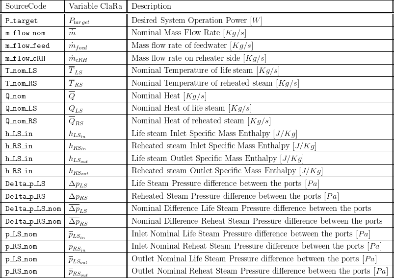
5. Nomenclature
6. Governing Equations
6.2 Governing Model Equations
The pressure differences for live steam and reheated steam are given from an interpolation table using for reference the rate of live mass steam with nominal mass flow  for the live steam pressure difference and
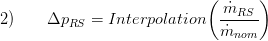
  for the reheated steam. These values are given to the interpolation to obtain:
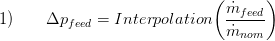
for the live steam and for the reheated steam,
The live steam heat ratio is given by  where
where  is given by the enthalpy difference times the mass flow of the live steam the expression for it is then,
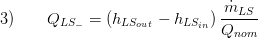
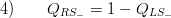
The reheated steam ratio is the rest of the heat produced in by the live steam ratio given by,
The enthalpies of the reheated outlet steam and live steam are functions of the pressures, temperatures and the medium,

the same for the reheated steam

The outlet and inlet pressures are given by the pressure differences and the nominal pressure ratios


The target power preserves the ratio of the quantities of the system, with this ratio the outer pressures are then computed,


7. Remarks for Usage
The model can only be connected with components with matching connector colour (see Example of Usage in StaticCycles)
9. References
[1] Johannes Brunnemann and Friedrich Gottelt, Kai Wellner, Ala Renz, André Thüring, Volker Röder, Christoph Hasenbein, Christian Schulze, Gerhard Schmitz, Jörg Eiden: "Status of ClaRaCCS: Modelling and Simulation of Coal-Fired Power Plants with CO2 capture", 9th Modelica Conference, Munich, Germany, 2012
10. Authorship and Copyright Statement for original (initial) Contribution
Author:
DYNCAP/DYNSTART development team, Copyright 2011 - 2025.
Remarks:
This component was developed during DYNCAP/DYNSTART projects.
Acknowledgements:
ClaRa originated from the collaborative research projects DYNCAP and DYNSTART. Both research projects were supported by the German Federal Ministry for Economic Affairs and Energy (FKZ 03ET2009 and FKZ 03ET7060).
CLA:
The author(s) have agreed to ClaRa CLA, version 1.0. See https://claralib.com/pdf/CLA.pdf
By agreeing to ClaRa CLA, version 1.0 the author has granted the ClaRa development team a permanent right to use and modify his initial contribution as well as to publish it or its modified versions under the 3-clause BSD License.
11. Version History
04.08.2014 - Version:1.0 - Timo Tumforde
Backlinks: ClaRa:StaticCycles