
CompressorVLE L1 stageStacked
Created Thursday 20 March 2014
A physical model for a VLE mixture compressor featuring part load behaviour of pressure ratio, mass flow and efficiency with static conservation of mass, energy and momentum. Variable inlet guide vanes can be considered.
1. Purpose of Model
The model is used to to simulate a detailed compressor with realistic part load behaviour of a typical axial or radial machine calculated with few given parameters.
2. Level of Detail, Physical Effects Considered and Physical Insight
2.1 Level of Detail
Referring to Brunnemann et al. [1], this model refers to the level of detail L1 because the system is modelled in an phenomenological manner, without calculating state equations. The model is of the flow model type. However, conservation of mass and energy is granted.
2.2 Physical Effects Considered
- Conservation of Mass (in steady state)
- Conservation of Momentum (in steady state)
- Conservation of Energy (in steady state)
- Hydraulic Efficiency
2.3 Level of Insight
- all balance equations are considered in a steady-state manner
3. Limits of Validity
- Backflow and zero mass flow is not supported.
- Only gaseous state of VLE mixtures are considered to calculate correct results.
- Flow velocity differences small.
- Difference between the heights of the ports small.
4. Interfaces
4.1 Physical Connectors
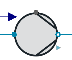
Basics:Interfaces:FluidPortIn inlet
Basics:Interfaces:FluidPortOut outlet
- Mechanical port for:
- Torque [Nm]
- Absolute rotation angle [rad]
4.2 Medium Models
- Medium models of the VLE mixture type are supported.
5. Nomenclature
6. Governing Equations
6.1 System Description and General model approach
This component represents a physical compressor model with realistic part load behaviour using the so called stage stacking method according to N. Gasparovic [2]. With this method the behaviour of a single compressor stage is calculated and summed up to achieve the behaviour of a multistage radial or axial compressor. With few parameters to be set for the point of highest efficiency a typical carachteristic can be calculated depending on the actual pressure ratio and drive speed of the machine where the isentropic efficiency depends on the actual flow parameters too. The influence of variable inlet guide vanes is implemented according to [3] and [4] and can be regarded in multiple stages. The deviation of different parameters due to changing variable inlet guide vane positions is regarded by polynomials derived from measurements given in [5]. If wanted a single stage characteristic can be calculated too[6]. The description of this method in detail would exceed this documentation. Please have a look at the given literature to get a closer look into the mentioned stage stacking method.
The model was compared with given data of an induced draft fan. Unfortunately the point of highest efficiency needed to parametrize the model could only be approximated. In the following image the results of different guide vane angles are plotted in blue across the given characteristic of the fan. The upper end values of the lines represent the calculated surge line.
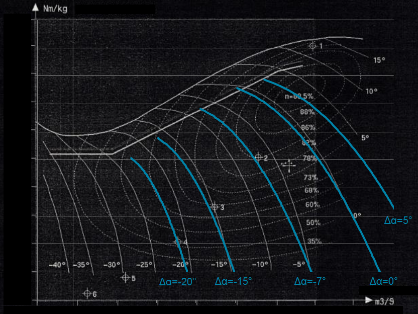
As could be seen there are differences between simulation and reference map. These result from the derived polynomials for the influence of variable inlet guide vanes especially above 10° and the parameter approximation for the point of highest compressor efficiency. Furthermore, the model itself just calculates a general compressor map which might not fit a real map because each machine has its own unique characteristic. Nevertheless this model is an excellent choice to calculate a physical compressor behaviour with only few typical parameters and without being dependent on manufacturer data.
Summary
A summary record is available which bundles important component values.
7. Remarks for Usage
- Stationary flow
- Compressible flow
- No backflow, no zero flow
9. References
[1] Johannes Brunnemann and Friedrich Gottelt, Kai Wellner, Ala Renz, André Thüring, Volker Röder, Christoph Hasenbein, Christian Schulze, Gerhard Schmitz, Jörg Eiden: "Status of ClaRaCCS: Modelling and Simulation of Coal-Fired Power Plants with CO2 capture", 9th Modelica Conference, Munich, Germany, 2012
[2] N. Gašparovic and D. Stapersma: "Berechnung der Kennfelder mehrstufiger axialer Turbomaschinen", Forschung im Ingenieurswesen, Band 39, 1973
[3] N. Gašparovic and J-W. Kim: "Kennfeldberechnung einstufiger Axialverdichter mit variabler Geometrie", Elektrizitätswirtschaft, Band 5, 1985
[4] H. Göttlich: "Verfahren zur Berechnung der Kennfelder von axialen bzw. radialen, ein oder mehrstufigen thermischen Strömungsmaschinen, auch unter Berücksichtigung des Einflusses von verstellbaren Leitapparaten", Dissertation, Technische Universität Berlin, 1984
[5] B. Eckert and E. Schnell: "Axial- und Radialkompressoren", Springer-Verlag, Berlin, Heidelberg, New York, 1961
[6] N. Gašparovic and H. Göttlich: "Kennfeldberechnung einstufiger Axialverdichter", BWK, Band 37, 1973
10. Authorship and Copyright Statement for original (initial) Contribution
Author:
DYNCAP/DYNSTART development team, Copyright 2011 - 2022.
Remarks:
This component was developed during DYNCAP/DYNSTART projects.
Acknowledgements:
ClaRa originated from the collaborative research projects DYNCAP and DYNSTART. Both research projects were supported by the German Federal Ministry for Economic Affairs and Energy (FKZ 03ET2009 and FKZ 03ET7060).
CLA:
The author(s) have agreed to ClaRa CLA, version 1.0. See https://claralib.com/pdf/CLA.pdf
By agreeing to ClaRa CLA, version 1.0 the author has granted the ClaRa development team a permanent right to use and modify his initial contribution as well as to publish it or its modified versions under the 3-clause BSD License.
11. Version History
Date - Version - Description of changes - author/revisor
25.06.2014 - v0.1 - initial implementation of the model - Lasse Nielsen, TLK-Thermo GmbH