
CompressorVLE L1 simple
Created Tuesday 22 February 2022
An analytic model for a pump featuring static conservation of mass, energy and momentum. Here the fluid is considered to be incompressible. Thus, the hydraulic characteristics of the pump are modelled taking a constant density into account. The effect of strongly reduced flow rates when steam is drawn into the inlet at constant rotational speed and pressure difference is caught qualitatively. The model is singular at zero mass flow rates.
1. Purpose of Model
The model is appropriate when the time behaviour of the flow rate and outlet states of a compressor depending on drive power and pressure difference is required and if the behaviour of the attached mechanical and electrical equipment is not of interest. If unusual operation (including failure with backflow or zero flow) or the behaviour of attached equipment is of interest, use PumpVLE L3_4Q.
2. Level of Detail, Physical Effects Considered and Physical Insight
2.1 Level of Detail
Referring to Brunnemann et al. [1], this model refers to the level of detail L1 because the system is modelled in an phenomenological manner, without calculating state equations. The model is of the flow model type. However, conservation of mass and energy is granted.
2.2 Physical Effects Considered
Please refer to PumpVLE L1_simple.
2.3 Level of Insight
Please refer to PumpVLE L1_simple.
3. Limits of Validity
- Backflow and zero mass flow is not supported.
- Flow velocity differences small.
- Difference between the heights of the ports small.
- Incompressible and compressible Flow.
4. Interfaces
Please refer to PumpVLE L1_simple.
5. Nomenclature
Please refer to PumpVLE L1_simple.
6. Governing Equations
In general the derived dynamical equations for the model consider the balance of certain properties like: mass, energy and momentum. For the model, mechanical and hydraulic efficiency of the compressor are used.
6.1 System Description and General model approach
The derived dynamical equations for the model are balances of mass, energy and momentum considering the mechanic and hydraulic efficiencies. There are no transient state variables defined, i.e. the model equations are purely algebraic.
6.2 Governing Model Equations
Energy Conservation
The constant energy balance of the compressor reads
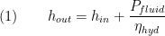
where the hydraulic power of the shaft given by the (constant) hydraulic and mechanic efficiency and the given drive power:

Please note that the backflow definition of the stream variable  is a dummy value since backflow is not supported.
Mass Conservation
Momentum Conservation
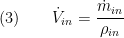
Hydraulics
The volume flow rate trough the system is given by
7. Remarks for Usage
- no backflow supported
- model is singular at Δp = 0 giving infinte volume flow.
9. References
[1] Johannes Brunnemann and Friedrich Gottelt, Kai Wellner, Ala Renz, André Thüring, Volker Röder, Christoph Hasenbein, Christian Schulze, Gerhard Schmitz, Jörg Eiden: "Status of ClaRaCCS: Modelling and Simulation of Coal-Fired Power Plants with CO2 capture", 9th Modelica Conference, Munich, Germany, 2012
10. Authorship and Copyright Statement for original (initial) Contribution
Author:
ClaRa development team, Copyright 2017 - 2025.
Remarks:
This component was developed for ClaRa library.
Acknowledgements:
CLA:
11. Version History
Date - Version - Description of changes - author/revisor
17.01.2022 - v0.1 - initial implementation of the model - Ales Vojacek, XRG Simulation
Backlinks: ClaRa:A User Guide:Revisions:v1.8.0