
AsynchronousMotor L2_base
Created Tuesday 15 July 2014
This is the base class for asynchronous electric motors.
1. Purpose of Model
This base class provides the basic equation for the simple asynchronous motor models.
2. Level of Detail, Physical Effects Considered and Physical Insight
2.1 Level of Detail
Referring to Brunnemann et al. [1], this model refers to the level of detail L2 because the system is modelled with the use of (mechanical) balance equation, which are spatially averaged over the component.
2.2 Physical Effects Considered
- mechanical energy storage
- electric performance according to simplified equivalent circuit diagram
- constant stator efficiency
2.3 Level of Insight
currently no different levels of insight are available for the considered physical effects
3. Limits of Validity
- no twisting of the shaft
4. Interfaces
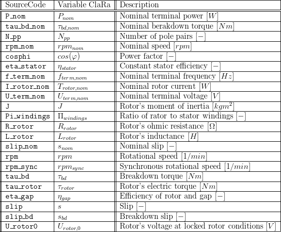
5. Nomenclature
a table referencing the nomenclature in the source code, the descriptions of variables and the "human-readable", use the following latex table template:
6. Governing Equations
6.1 System Description and General Modelling Approach
The model is based on the simplified equivalent circuit shown below. Based on the theories of phase vector representation common to AC electric engineering the performance of the electric machine is derived. Storage of mechanical energy is considered applying an energy balance for the total system.
6.2 General Model Equations
Definitions
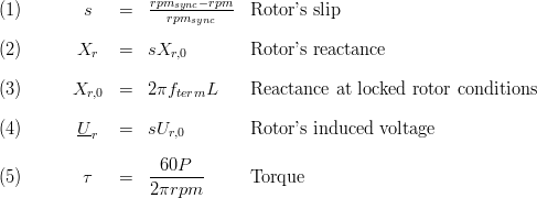
Electric Characteristics
The electric performance characteristics are mostly taken from [2]. Basis for the calculation of the electric performance is the following simplified equivalent circuit:
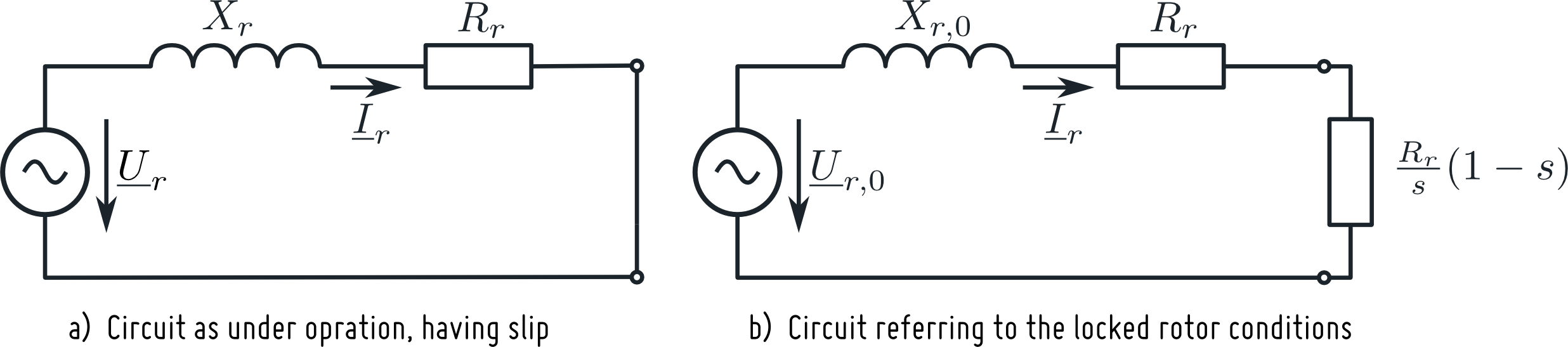
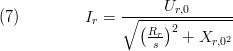
From the above figure the locked rotor induced voltage can be derived as
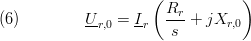 . The absolute value of the induced rotor current is (under the definition that the phase angle of the current is zero) then
 and the gap power:
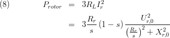
Applying definitions (1) and (5) the gap torque reads:
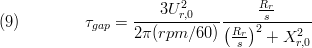
The above formula has a maximum, defined by  . Curve sketching gives these values. The breakdown torque depends on locked rotor voltage, synchronous speed, and the rotor's inductance:
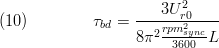 .
.
The breakdown slip is depending on the excitation frequency, the rotor's ohmic resistance and its inductance:
 .
.
In the above equation the locked rotor voltage depends on the terminal voltage and the ratio of rotor windings to anchor windings is implied be the AC transformer's basic equations:
 .
.
sub-dividing equation (9) by equation (10) gives us the actual gap torque:
 ,
,
which is called the formula of Kloss
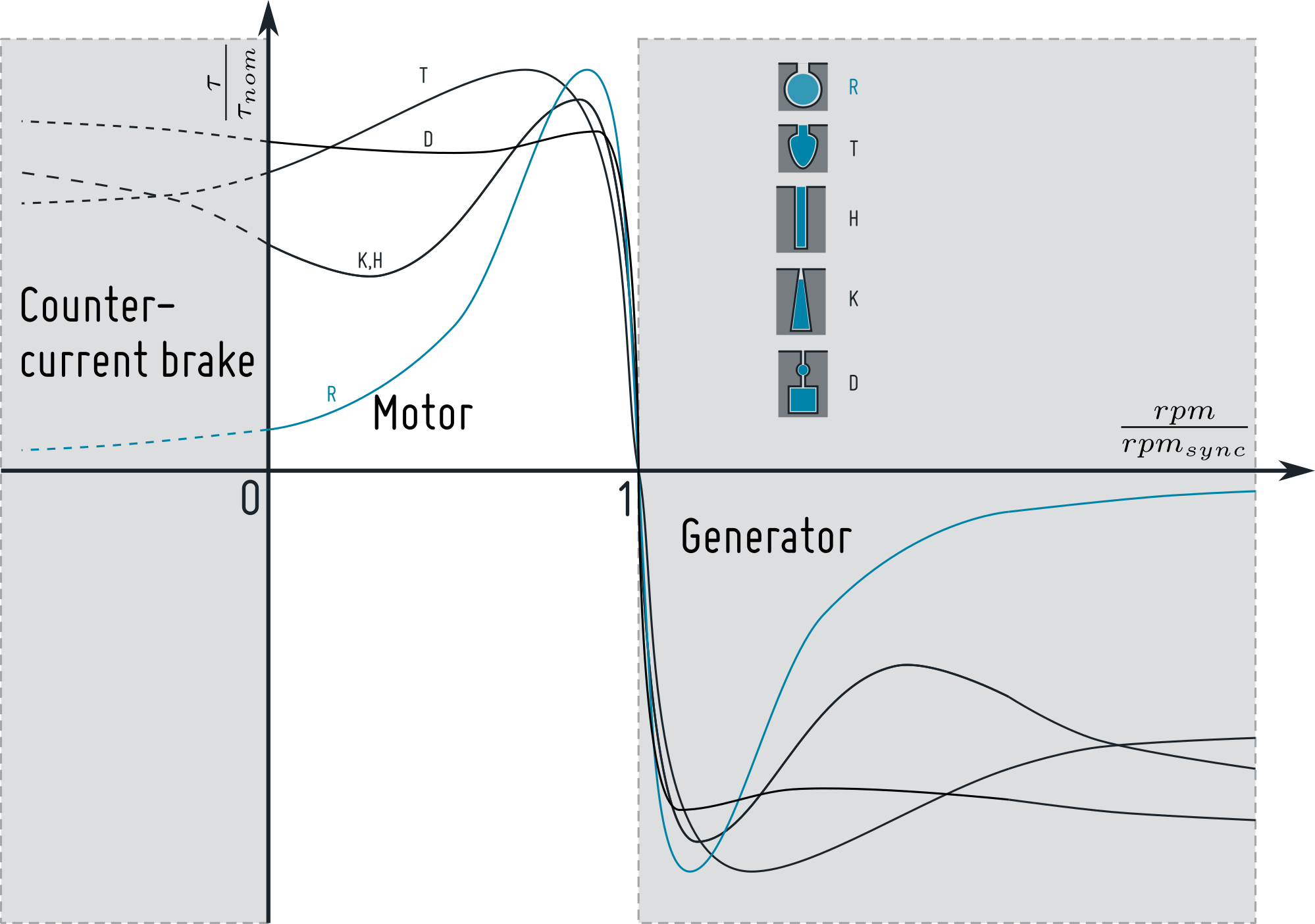
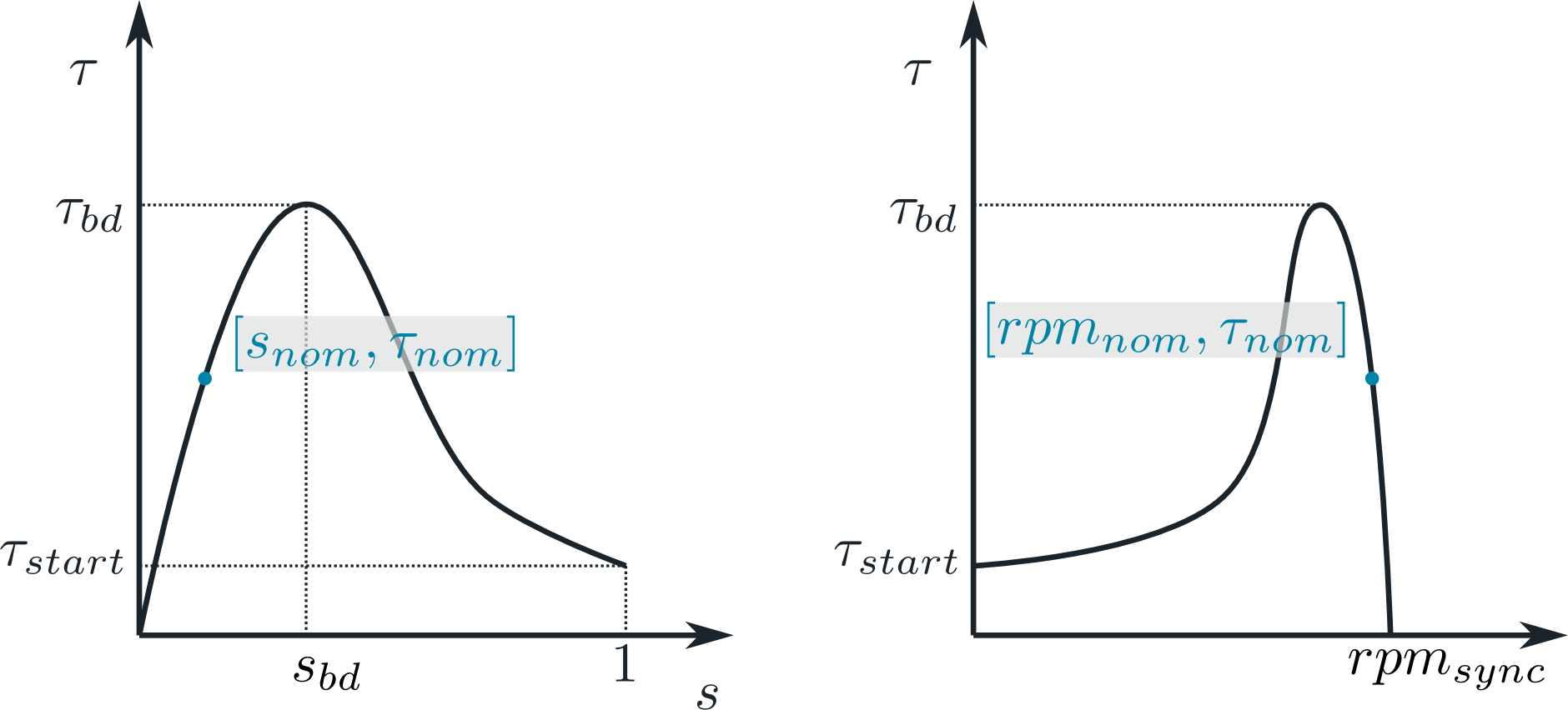
This equation (13) correlates the actual slip (and thereby the rotational speed) with the torque. Please note that this characteristic line is a function of the rotor bar geometry according to [2] five different geometries can be distinguished leading to different torque speed curves, see figure below. Due to the fact that the formula of Kloss refers to the rotor bar of type "R" (marked blue in the figure) which is quite disadvantageous regarding the starting torque the user can also define a specific characteristic line in a table when setting useCharLine = true. According to [4] three different operation modes can be distingueshed: The nomal motor operation (tau > 0 and rpm > 0), the generator operation (tau < 0, rpm > 0) and the counter current brake (tau > 0 and rpm < 0), see figure below. The according behaviour is fewatured from version 1.4.0 on.
The table definition will be applied as follows:

herein the function tableIpo will perform a linear interpolation of the table's entries. The interpolation will be smooth when smoothness is set accordingly in the expert settings. Please note, the formula of Kloss implies a frequency dependency of the break down slip. This is not considered when applying the table-based characteristics.
Mechanic Energy Conservation

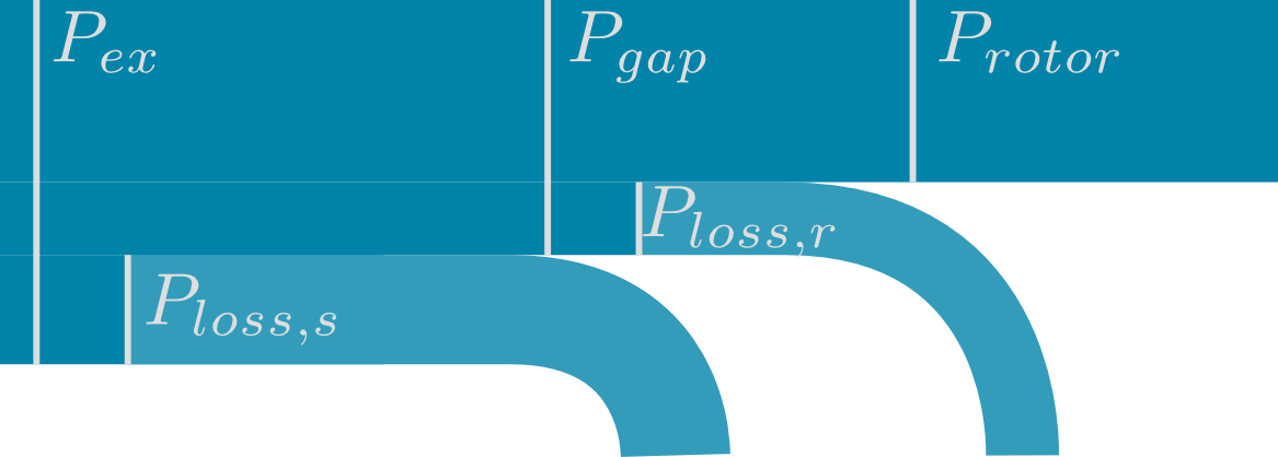
Losses and Power Flow
The following simplified Sankey diagram illustrates the losses taken into account. The ideas for modelling the losses are taken from [3].
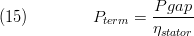
Stator Losses:
For the sake of simplicity the stator's efficiency is assumed to be constant. The terminal power is therefore
Rotor Losses:
Assuming no stray losses the rotor losses can be summarised as
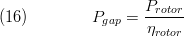 .
.
Thus we can introduce a rotor efficiency:

7. Remarks for Usage
For the sake of usability the parameter dialog refers to values that are likely available for the user through the product data sheet of a specific motor:
The ratio of rotor to stator windings used in equation (12) is calculated
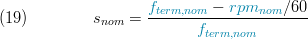
From the nominal excitation frequency and the nominal speed and the number of pole pairs the nominal slip can be determined:
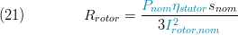
The ohmic resistance of the rotor can be derived from equations (15) to (17) and (8) under the nominal point conditions:
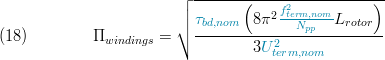
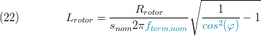
From normal power, power factor, slip and excitation frequency we can obtain the rotor's inductance:
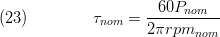
When using table-based characteristics the nominal torque is calculated from the nominal power and speed:
8. Validation
9. References
[1] Johannes Brunnemann and Friedrich Gottelt, Kai Wellner, Ala Renz, André Thüring, Volker Röder, Christoph Hasenbein, Christian Schulze, Gerhard Schmitz, Jörg Eiden: "Status of ClaRaCCS: Modelling and Simulation of Coal-Fired Power Plants with CO2 capture", 9th Modelica Conference, Munich, Germany, 2012.
[2] Rolf Fischer, Hermann Linse: "Elektrotechnik für Maschinenbauer - Mit Elektronik, elektrischer Messtechnik, elektrischen Antrieben und Steuerungstechnik", 14th edition, Springer, 2012.
[3] Wilfried Hofmann: "Elektrische Maschinen - Lehr und Übungsbuch", 1st edition, Pearson, 2013.
[4] U. Beckert: "Asynchronmotor - Stationäres Betriebsverhalten, Skriptum für Nichtelektrotechniker", https://tu-freiberg.de/sites/default/files/media/institut-fuer-elektrotechnik-12774/UBeckert_Scr/asm_stat_verhalten.pdf, TU Bergakademie Freiberg Institut für Elektrotechnik, 2005
10. Authorship and Copyright Statement for original (initial) Contribution
Author:
DYNCAP/DYNSTART development team, Copyright 2011 - 2025.
Remarks:
This component was developed during DYNCAP/DYNSTART projects.
Acknowledgements:
ClaRa originated from the collaborative research projects DYNCAP and DYNSTART. Both research projects were supported by the German Federal Ministry for Economic Affairs and Energy (FKZ 03ET2009 and FKZ 03ET7060).
CLA:
The author(s) have agreed to ClaRa CLA, version 1.0. See https://claralib.com/pdf/CLA.pdf
By agreeing to ClaRa CLA, version 1.0 the author has granted the ClaRa development team a permanent right to use and modify his initial contribution as well as to publish it or its modified versions under the 3-clause BSD License.
11. Version History
- 2014-July-15 - v0.0 - Initial implementation - F. Gottelt, XRG Simulation GmbH
- 2014-August-25 - v0.1 - added table-based characteristcs - F. Gottelt, XRG Simulation GmbH
- 2018-03-14 - v1.3.0 - introduced base class of asynchronous motors - T.Hoppe, XRG Simulation GmbH
- 2019-01-17 - v1.4.0 - featuring of reverse rotation and zero rotation - F. Gottelt, XRG Simulation GmbH
Backlinks: ClaRa:Components:Electrical:AsynchronousMotor L2