
AsynchronousMotor_L2
Created Mittwoch 14 März 2018
A simple asynchronous electric motor with excitation voltage and frequency set by input.
1. Purpose of Model
This model is applicable in cases where the performance of the electric machines influences the steam cycle's transients. For example think of a fast pressure increase in a feedwater pipe. In this case the increasing fluid torque might cause the pump to decelerate due to limited torque at the motor side. This will in turn reduce the fluid mass flow due to changed operation speed (additionally to the effect of reduced mass flow due to the increasing pressure difference).
2. Level of Detail, Physical Effects Considered and Physical Insight
2.1 Level of Detail
Referring to Brunnemann et al. [1], this model refers to the level of detail L2 because the system is modelled with the use of (mechanical) balance equation, which are spatially averaged over the component.
2.2 Physical Effects Considered
- mechanical energy storage
- electric performance according to simplified equivalent circuit diagram
- constant stator efficiency
2.3 Level of Insight
currently no different levels of insight are available for the considered physical effects
3. Limits of Validity
- no twisting of the shaft
4. Interfaces
The following connectors are available:
- Modelica.Mechanics.Rotational.Interfaces.Flange_a shaft - mechanical connector based on the Modelica standard library
- Modelica.Blocks.Interfaces.RealInput U_ex - Excitation voltage
- Modelica.Blocks.Interfaces.RealInput f_ex - Excitation frequency
- ClaRa.Basics.Interfaces.HeatPort_a heat - optional connector, an be activated by setting the boolean parameter activateHeatPort to true
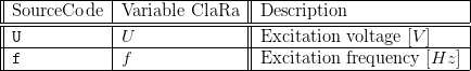
5. Nomenclature
6. Governing Equations
6.1 System Description and General Modelling Approach
The model extends the AsynchronousMotor L2 base model. See according documentation for a detailed description of the underlying model equations.
The model requires the excitation voltage  and the excitation frequency
  as inputs.
7. Remarks for Usage
For the sake of usability the parameter dialog refers to values that are likely available for the user through the product data sheet of a specific motor. See the remarks of the documentation of AsynchronousMotor L2 base for calculation of these values.
8. Validation
9. References
[1] Johannes Brunnemann and Friedrich Gottelt, Kai Wellner, Ala Renz, André Thüring, Volker Röder, Christoph Hasenbein, Christian Schulze, Gerhard Schmitz, Jörg Eiden: "Status of ClaRaCCS: Modelling and Simulation of Coal-Fired Power Plants with CO2 capture", 9th Modelica Conference, Munich, Germany, 2012.
10. Authorship and Copyright Statement for original (initial) Contribution
Author:
DYNCAP/DYNSTART development team, Copyright 2011 - 2025.
Remarks:
This component was developed during DYNCAP/DYNSTART projects.
Acknowledgements:
ClaRa originated from the collaborative research projects DYNCAP and DYNSTART. Both research projects were supported by the German Federal Ministry for Economic Affairs and Energy (FKZ 03ET2009 and FKZ 03ET7060).
CLA:
The author(s) have agreed to ClaRa CLA, version 1.0. See https://claralib.com/pdf/CLA.pdf
By agreeing to ClaRa CLA, version 1.0 the author has granted the ClaRa development team a permanent right to use and modify his initial contribution as well as to publish it or its modified versions under the 3-clause BSD License.
11. Version History
- 2014-July-15 - v0.0 - Initial implementation - F. Gottelt, XRG Simulation GmbH
- 2014-August-25 - v0.1 - added table-based characteristcs - F. Gottelt, XRG Simulation GmbH
- 2018-03-14 - v1.3.0 - introduced base class of asynchronous motors - T.Hoppe, XRG Simulation GmbH
Backlinks: ClaRa:A User Guide:Revisions:v1.0.0 ClaRa:Components:TurboMachines:Pumps:PumpVLE L1 affinity