
ThickWall L4
Created Thursday 13 June 2013
Model energy storage and heat flow in radial direction through a cylindric wall
1. Purpose of Model
This model is appropriate if energy storage in a wall is of relevance and if the temperature gradients in radial direction are large compared to the gradients in longitudinal direction. Typical examples are unheated, thick-walled components like headers.
2. Level of Detail, Physical Effects Considered and Physical Insight
2.1 Level of Detail
Referring to Brunnemann et al. [1], this model refers to the level of detail L4 because the system is modelled with the use of balance equations, which are spatially discretised. The discretisation scheme can be defined by the user.
2.2 Physical Effects Considered
- heat transfer due to conduction
- energy storage
2.3 Level of Insight
No different levels of detail available.
3. Limits of Validity
In case of rapid temperature transients at the connectors, discretisation should be chosen sufficiently fine (=small thermal capacities), such that adjacent cells quickly reach thermal equilibrium.
4. Interfaces
4.1 Physical Connectors
- Heat connectors combined for:
- Temperature in the connection port [K].
- Heat flow rate [Watt]. 1-dimensional heat flow between components at the connection port.
- Solid Material Model.
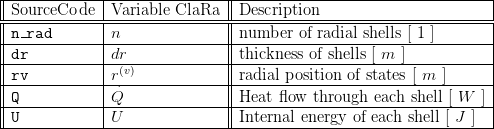
5. Nomenclature
6. Governing Equations
By construction, the model agrees in the stationary case with the analytic solution for temperature distribution and heat flow.
This holds independently of the discretisation.
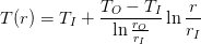
In the stationary case, at constant and temperature independent heat conductivity  one obtains for one solid cylinder the temperature distribution:
and a constant radial heat flow:
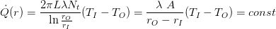
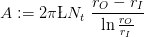
Here we have introduced the effective heat conduction surface
If heat conductivity varies from shell to shell (e.g. due to temperature dependence) then
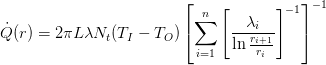
which is nothing but the heat flow through a series arrangement of heat resistors (one for each shell). Notice that here due to the finite volume approach the material properties are taken as spatially constant across each shell.
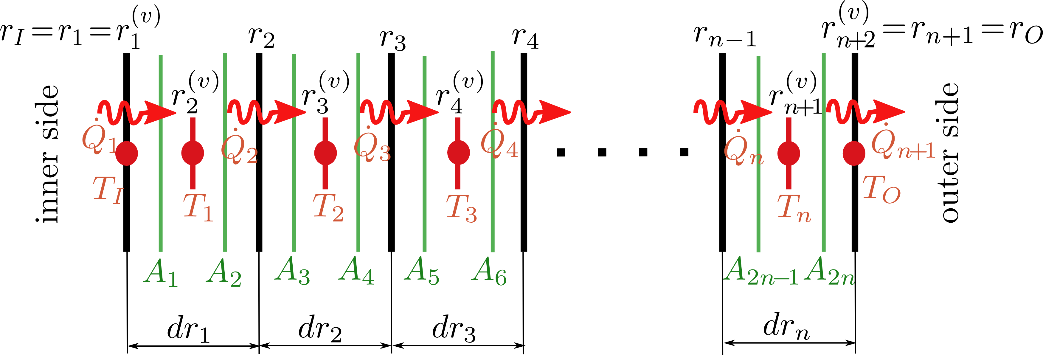
6.1 System Description and General model approach
The wall is decomposed into  radial shells, numbered from the inner side to the outer side from
  .
.
Shell number  has the thickness
  an cell borders
  and
and  . Moreover it has a temperature state
  , which is located at radius
 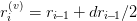 , which is the center of the cell.
6.2 General Model Equations
Energy Conservation
Each shell has a dynamic energy balance
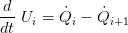
where the inner energy changes due to the heat flows across the shell borders and is given by

If the parameter  then it is multiplied with the heat capacity and distributed evenly to the inner energy of each shell.
In the model it is assumed that the radial discretisation is sufficiently fine, such that the heat flow between two adjacent cells can be assumed as stationary.
However, since in principle the heat conductivity in each cell can vary with temperature, each heat flow across a shell border is modelled as a serial connection of two heat resistors (one for each half shell)
(i=2...n) :
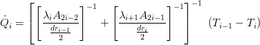
where the first term on the right hand side accounts for the distance between cell center i-1 and cell border and the second terms accounts for the distance between the cell border and the cell center i.
For the heat flow at the inner side (i=1) and outer side (i=n+1) we take:
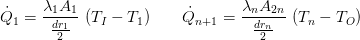
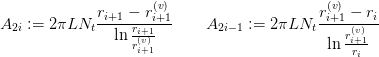
Accordingly the effective heat conduction surfaces are computed as (i=1..n)
7. Remarks for Usage
By construction, the model agrees in the stationary case with the analytic solution for temperature distribution and heat flow.
This holds independently of the discretisation.
8. Validation
9. References
[1] Johannes Brunnemann and Friedrich Gottelt, Kai Wellner, Ala Renz, André Thüring, Volker Röder, Christoph Hasenbein, Christian Schulze, Gerhard Schmitz, Jörg Eiden: "Status of ClaRaCCS: Modelling and Simulation of Coal-Fired Power Plants with CO2 capture", 9th Modelica Conference, Munich, Germany, 2012
10. Authorship and Copyright Statement for original (initial) Contribution
Author:
DYNCAP/DYNSTART development team, Copyright 2011 - 2025.
Remarks:
This component was developed during DYNCAP/DYNSTART projects.
Acknowledgements:
ClaRa originated from the collaborative research projects DYNCAP and DYNSTART. Both research projects were supported by the German Federal Ministry for Economic Affairs and Energy (FKZ 03ET2009 and FKZ 03ET7060).
CLA:
The author(s) have agreed to ClaRa CLA, version 1.0. See https://claralib.com/pdf/CLA.pdf
By agreeing to ClaRa CLA, version 1.0 the author has granted the ClaRa development team a permanent right to use and modify his initial contribution as well as to publish it or its modified versions under the 3-clause BSD License.
11. Version History
2013-06-28 - v 0.1 - Initial implementation - Johannes Brunnemann, XRG Símulation
24.04.2017 - v1.2.2 - parameter mass_struc added, the additional mass is evenly distributed to each shell - Timm Hoppe, XRG Simulation
Backlinks: ClaRa:Basics:ControlVolumes:SolidVolumes:ThinWall L2