
NTU L3
Created Wednesday 25 July 2012
Heat transfer resistance of a heat exchanger with phase change based on the concepts of Number of Transfer Units (NTU). This model requires area fractions of the distinct zones be given as input. The model must be applied together with another model providing these area fractions.
1. Purpose of Model
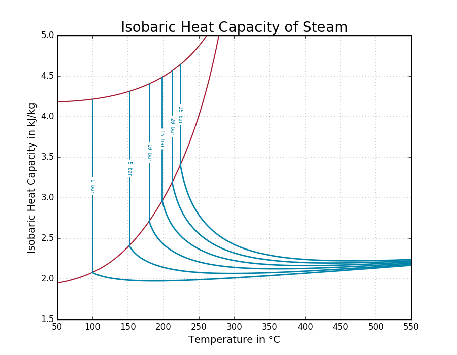
The main purpose of the NTU 3-zones model is to realise a heat exchanger with phase change and additionally to achieve more accurate values for medium properties and heat transfer coefficients. The following figure shows the isobaric specific heat capacity for water dependent on the temperature. The strong non-linearity leads to a major disadvantage of the NTU model particularly in the gaseous phase. The liquid saturation line is represented by the blue line whereas the vapour saturation is represented by the red line. The black lines are the lines of equal pressure (isobaric). The main idea of the NTU_L3 is to divide the diagram into three parts, the liquid, the two-phase and the gaseous phase and to handle each part separately. The averaging, however it is executed, will provide a better result.
2. Level of Detail, Physical Effects Considered and Physical Insight
2.1 Level of Detail
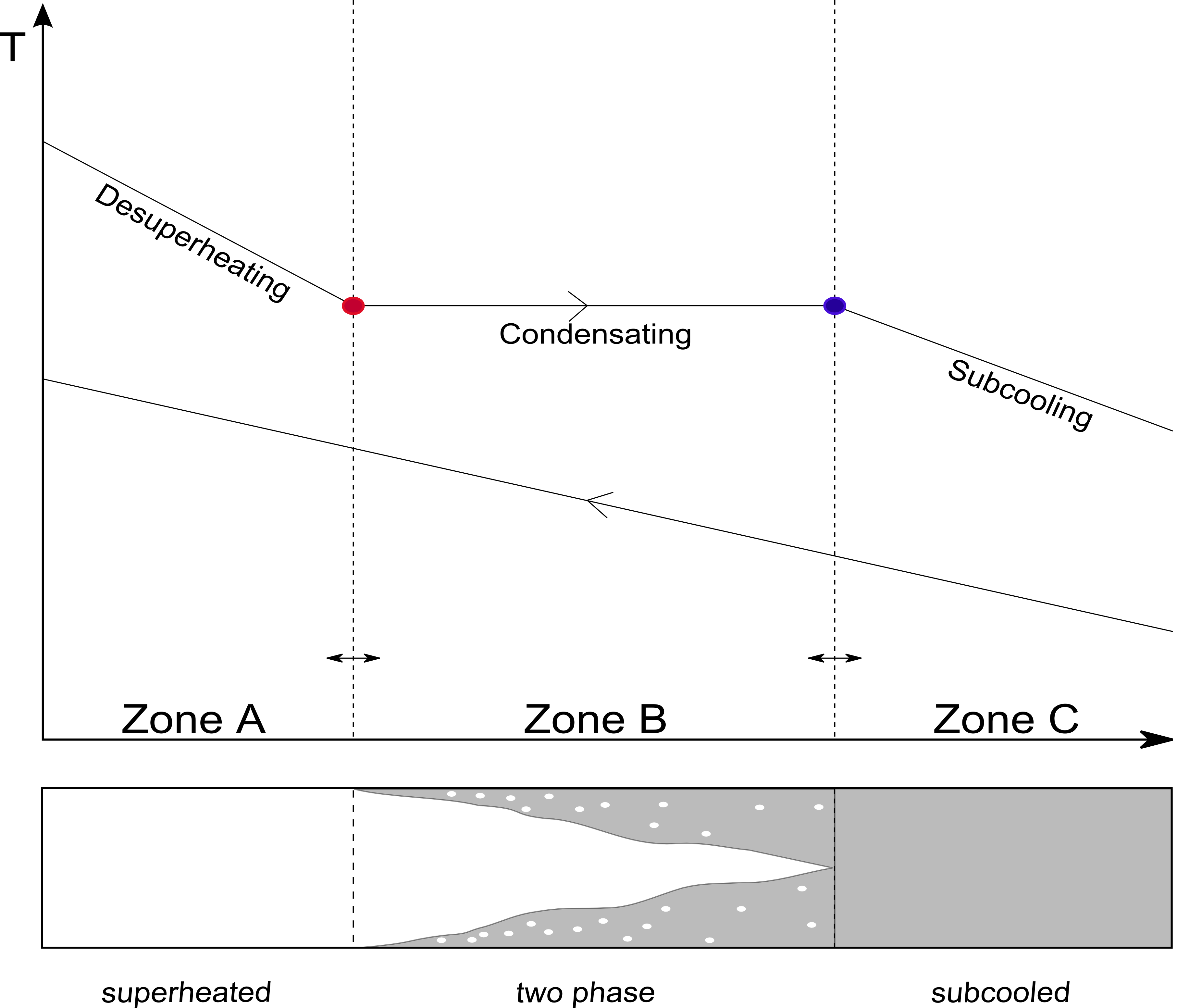
Referring to Brunnemann et al. [1], this model refers to the level of detail L3 because the system is modelled distinguishing three distinct zones, namely the vapour zone, the two-phase zone and the liquid zone.
2.2 Physical Effects Considered
- steady state operation at both side and the separating wall
- constant fluid properties with respect to time and spacial extension for each zone
- applying spacial averaged heat transfer coefficients for each zone
- the only heat exchange is between hot and cold fluids
- no axial conduction along the tubes
- Pressure loss is neglected
- Kinetic and Potential energy are neglected
- two 0D energy balances for closed systems are applied to model the energy storage in the walls. Their exact geometric position in flow direction of the solid states can not be quantified and may be referred to as a virtual mean temperature. However, the solid temperatures are used as boundaries for the corresponding fluid models and are this way located at the inner and outer side, respectively.
2.3 Level of Insight
Heat exchanger type
3. Limits of Validity
Nearly constant fluid properties can be assumed for pure liquids. Heat exchangers operating with phase change or in gases or liquids near the saturation line will lead to lower accuracy.
4. Interfaces
In the parameter dialog a number of inputs is expected, which interface the corresponding fluid volumes:
- Inlet specific enthalpy at each side
- Pressure at each side
- Inlet specific heat capacity at each side
- Mass flow rate at each side
- heat transfer coefficient at each side
- Area fraction for each zone
- Geometry parameters
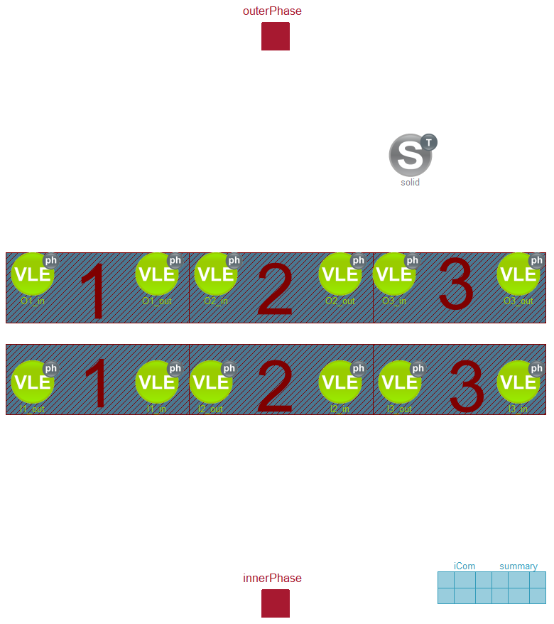
The figure below shows the modular composition of the NTU L3 base model in the diagram view. The two red rectangles are the heat ports, the green circles are the medium models to calculate the medium state for the fluid at the boundaries and a gray circle for solid state.
5. Nomenclature
6. Governing Equations
6.1 System Description and General model approach
6.2 General Model Equations
This section will be revised due to introduction of replaceable models for the different geometries.
Zone determination
The area fraction of the three zones are expected to be given as an input, in NTU L3 standalone a simple transparent idea is described determining the area fractions based on PI controllers.
Correction Factor
Due to deviations of the specific heat capacity a correction factor is applied.
  Q_flow_A  = Psi_A * W_flow_A_low * (A_o_in.T - B_i_out.T) * noEvent(max(0,homotopy(1-10000*max(0,min(1,effectivenes_A-1)),1)));
  Q_flow_B  = Psi_B * W_flow_B_low * (B_o_in.T - B_i_in.T)  * noEvent(max(0,homotopy(1-10000*max(0,min(1,effectivenes_B-1)),1)));
  Q_flow_C  = Psi_C * W_flow_C_low * (B_o_out.T - C_i_in.T) * noEvent(max(0,homotopy(1-10000*max(0,min(1,effectivenes_C-1)),1)));
Summary
7. Remarks for Usage
- the performance of heat exchangers using this heat resistance model can be displayed using Visualisation:HexDisplay L3
- the model approach is accurate for steady state operation, i.e. load changes with sufficiently slow transients will be modelled with small errors
- nearly constant fluid properties can be assumed for pure liquids. Heat exchangers operating with phase change or in gases or liquids near the saturation line will lead to lower accuracy
8. Validation
9. References
[1] Johannes Brunnemann and Friedrich Gottelt, Kai Wellner, Ala Renz, André Thüring, Volker Röder, Christoph Hasenbein, Christian Schulze, Gerhard Schmitz, Jörg Eiden: "Status of ClaRaCCS: Modelling and Simulationof Coal-Fired Power Plants with CO2 capture", 9th Modelica Conference, Munich, Germany, 2012
[2] Verein Deutscher Ingenieure: "VDI Heat Atlas", chapter Ca: 'Calculation of Heat Exchangers' (in German), 9th edition, Springer 2002
10. Authorship and Copyright Statement for original (initial) Contribution
Author:
DYNCAP/DYNSTART development team, Copyright 2011 - 2025.
Remarks:
This component was developed during DYNCAP/DYNSTART projects.
Acknowledgements:
ClaRa originated from the collaborative research projects DYNCAP and DYNSTART. Both research projects were supported by the German Federal Ministry for Economic Affairs and Energy (FKZ 03ET2009 and FKZ 03ET7060).
CLA:
The author(s) have agreed to ClaRa CLA, version 1.0. See https://claralib.com/pdf/CLA.pdf
By agreeing to ClaRa CLA, version 1.0 the author has granted the ClaRa development team a permanent right to use and modify his initial contribution as well as to publish it or its modified versions under the 3-clause BSD License.
11. Version History
- 17.08.2012 - Version 0.1 - Ala Renz/Friedrich Gottelt, XRG Simulation GmbH
Backlinks: ClaRa:Components:HeatExchangers:HEXvle2vle L3 2ph BU ntu ClaRa:Components:HeatExchangers:HEXvle2vle L3 2ph CH ntu ClaRa:Components:HeatExchangers:HEXvle2vle L3 2ph CU ntu ClaRa:Basics:ControlVolumes:SolidVolumes:NTU L3 standalone ClaRa:Basics:ControlVolumes:SolidVolumes:NTU plate L3