VolumeGas L4
Created Monday 24 March 2014
Basic model of a discretized gas volume with dynamic energy and mass balances, taking convective heat transfer and pressure losses into account.
1. Purpose of Model
The model is used as a basic model to form different discretized components which handle gaseous media.
2. Level of Detail, Physical Effects Considered and Physical Insight
2.1 Level of Detail
Referring to Brunnemann et al. [1], this model refers to the level of detail L4.
2.2 Physical Effects Considered
- Conservation of Mass
- Conservation of Energy
- Reverse flow
- Heat Transport due to convection
- Pressure loss due to friction
2.3 Level of Insight
Heat Transfer
- ControlVolumes:Fundamentals:HeatTransport:Generic HT:Adiabat L4
- ControlVolumes:Fundamentals:HeatTransport:Generic HT:IdealHeatTransfer L4
- ControlVolumes:Fundamentals:HeatTransport:Generic HT:Constant L4
- ControlVolumes:Fundamentals:HeatTransport:Generic HT:NominalPoint L4
Pressure Loss
- ControlVolumes:Fundamentals:PressureLoss:Generic PL:NoFriction L4
- ControlVolumes:Fundamentals:PressureLoss:Generic PL:LinearPressureLoss L4
- ControlVolumes:Fundamentals:PressureLoss:Generic PL:QuadraticNominalPoint L4
Geometry
- Generic_Geometry : Generic geometry
- HollowBlock : Geometry of a hollow block
- HollowBlockWithTubes : Geometry of a hollow block with tubes inside
- Pipe_Geometry : Geometry of a pipe
3. Limits of Validity
- Steady flow.
- Fixed control volume.
- Averaging assumption violated.
- The equations imply that the outlet states equal the states in the balance equations - Not true for large volumes and high gradients.
4. Interfaces
4.1 Physical Connectors
Basics:Interfaces:GasPortIn inlet
Basics:Interfaces:GasPortOut outlet
Basics:Interfaces:HeatPort a heat
4.2 Medium Models
- Gas Medium Model at the inlet and outlet port and inside the cells.
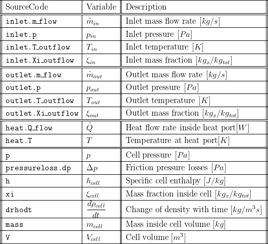
5. Nomenclature

6. Governing Equations
6.1 System Description and General model approach
The model describes an ideally stirred volume element with heat transfer to the surrounding.
6.2 Governing Model Equations
In the following, the index i indicates the single volumes of the discretized cell. In- and outflowing values are the corresponding in- and outflowing values of the previous or following volume.
Conservation of Mass
Via parameter preset the user can determine whether the mass balance is calculated dynamic or static. The dynamic mass balance is calculated as follows:

and the static mass balance:

Conservation of Momentum
We use balance of stationary momentum to model the pressure losses inside the control volume. The frictional pressure losses are calculated with the replaceable pressure loss models. Geodaetic pressure differences are calculated with inlet and outlet height. In the model the pressure distribution is given by the influence of friction in the x direction, which is given with the direction of the flow. In the parameter settings can be chosen at which positions the friction pressure losses are lumped (inlet, outlet or both).

Conservation of Energy
The energy balance considers ingoing and outgoing enthalpy flow rates as well as energy transport to the surrounding ( ). Please note the special structure of the energy balance with the differences of ingoing and outgoing enthalpies and the cell enthalpy and the additional term for the pressure derivative which is derived from the total derivative of the inner energy of the cell. The structure results from to the special choice of state variables as discussed in Basic Concepts of Modelling.

The model's density is taken as an explicit function of the states its total derivative should be used for completeness of the model given by:

while for stationary mass balance the following equation is used:

Conservation of Gas Components
The composition is a vector of the component mass fractions. The calculation of the outlet composition depends on the type of mass conservation. If the dynamic mass balance is used, the outlet composition is calculated as follows:

while for static mass balance the following equation is used:

Summary
A summary record is available which bundles important component values.
7. Remarks for Usage
This model is applied in a other component models either via instantiation of inheritance.
9. References
[1] Johannes Brunnemann and Friedrich Gottelt, Kai Wellner, Ala Renz, André Thüring, Volker Röder, Christoph Hasenbein, Christian Schulze, Gerhard Schmitz, Jörg Eiden: "Status of ClaRaCCS: Modelling and Simulation of Coal-Fired Power Plants with CO2 capture", 9th Modelica Conference, Munich, Germany, 2012
10. Authorship and Copyright Statement for original (initial) Contribution
Author:
DYNCAP/DYNSTART development team, Copyright 2011 - 2022.
Remarks:
This component was developed during DYNCAP/DYNSTART projects.
Acknowledgements:
ClaRa originated from the collaborative research projects DYNCAP and DYNSTART. Both research projects were supported by the German Federal Ministry for Economic Affairs and Energy (FKZ 03ET2009 and FKZ 03ET7060).
CLA:
The author(s) have agreed to ClaRa CLA, version 1.0. See https://claralib.com/pdf/CLA.pdf
By agreeing to ClaRa CLA, version 1.0 the author has granted the ClaRa development team a permanent right to use and modify his initial contribution as well as to publish it or its modified versions under the 3-clause BSD License.
11. Version History
Date - Version - Description of changes - author/revisor
- 2013-07-04 - v0.1 - initial implementation - Lasse Nielsen, TLK-Thermo GmbH
Backlinks: ClaRa:A User Guide:Revisions:v1.7.0 ClaRa:Components:HeatExchangers:FlatTubeFinnedHEXvle2gas L4 ClaRa:Components:HeatExchangers:RegenerativeAirPreheaterSecAir L4 ClaRa:Components:HeatExchangers:RegenerativeAirPreheater L4 ClaRa:Components:VolumesValvesFittings:Pipes:PipeFlowGas L4 Simple
