
Preheater1
Created Monday 04 August 2014
A stationary model of a preheater computing the specific enthalpies at tapping and condensate outlet.
1. Purpose of Model
The model is supposed to be used for the simplified simulation of static cases. Its main purpose is to provide appropriate start or nominal values for similar dynamic model versions.
It computes the stationary values of:
- Outlet mass specific enthalpy.
- Condensed outlet mass specific enthalpy.
2. Level of Detail, Physical Effects Considered and Physical Insight
2.1 Level of Detail
Referring to Brunnemann et al. [1], this model refers to the level of detail L1 because the model only computes a set of parameters for the given scenario.
2.2 Physical Effects Considered
- Conservation of Energy
3. Limits of Validity
The model is only able to calculate stationary situations.
4. Interfaces
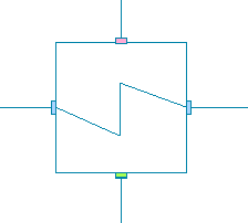
4.1 Steam Signals
For details see SteamSignal_blue, SteamSignal_red and SteamSignal_green.
Tapping inlet: Red connector
Tapping outlet: Green connector
Condensate inlet: Blue connector
Condensate outlet: Blue connector
4.2 Medium Models
VLE medium model
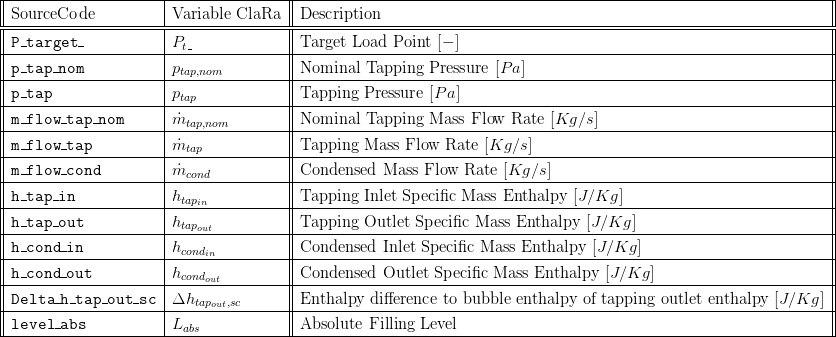
5. Nomenclature
6. Governing Equations
In general the derived equations for the model consider stationary balance of energy.
6.1 Governing Model Equations
Shell Side
The nominal tapping mass flow is set by the user via a parameter. A load dependent table is used to calculate the part load mass flow rate.

The nominal tapping pressure is set by the user via a parameter. A load dependent table is used to calculate the part load pressure.

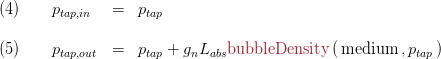
The tapping outlet enthalpy is given as the bubble enthalpy at the tapping pressure, reduced by the user parameter 

The pressure at the tapping inlet and outlet connector are given by
Tube Side
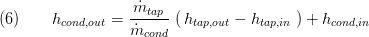
For computing the condenser outlet enthalpy the tapping enthalpies are balanced and multiplied by the value of the tapping mass flow as shown in eq. 2).
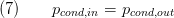
The inlet pressure at tube side equals the outlet pressure:
Summary
A summary is available including the following:
- Basics:Records:StaCyFlangeVle cond_inlet, cond_outlet, tap_inlet, tap_outlet
7. Remarks for Usage
- The model can only be connected with components with matching connector colour (see Example of Usage in StaticCycles).
9. References
[1] Johannes Brunnemann and Friedrich Gottelt, Kai Wellner, Ala Renz, André Thüring, Volker Röder, Christoph Hasenbein, Christian Schulze, Gerhard Schmitz, Jörg Eiden: "Status of ClaRaCCS: Modelling and Simulation of Coal-Fired Power Plants with CO2 capture", 9th Modelica Conference, Munich, Germany, 2012
10. Authorship and Copyright Statement for original (initial) Contribution
Author:
DYNCAP/DYNSTART development team, Copyright 2011 - 2025.
Remarks:
This component was developed during DYNCAP/DYNSTART projects.
Acknowledgements:
ClaRa originated from the collaborative research projects DYNCAP and DYNSTART. Both research projects were supported by the German Federal Ministry for Economic Affairs and Energy (FKZ 03ET2009 and FKZ 03ET7060).
CLA:
The author(s) have agreed to ClaRa CLA, version 1.0. See https://claralib.com/pdf/CLA.pdf
By agreeing to ClaRa CLA, version 1.0 the author has granted the ClaRa development team a permanent right to use and modify his initial contribution as well as to publish it or its modified versions under the 3-clause BSD License.
11. Version History
04.08.2014 - Version:1.0 - initial implementation - Timo Tumforde, XRG Simulation GmbH
29.07.2016 - Version 1.1.1 - removed parameter setMassFlow as setting it to false is not valid - Friedrich Gottelt, XRG Simulation GmbH
11.10.2016 - Version 1.2 - added part load functionality and level dependent outlet pressure - Timm Hoppe, XRG Simulation GmbH
02.06.2017 - Version 1.2.2. - added user parameter to define subcooling of tapping outlet enthalpy
Backlinks: ClaRa:StaticCycles