
GasTurbine L1 stageStacked
Created Samstag 01 Juli 2017
A physical model for a gas turbine featuring part load behaviour of pressure ratio, mass flow and efficiency with static conservation of mass, energy and momentum. Variable inlet guide vanes can be considered.
1. Purpose of Model
The model is used to to simulate a detailed turbine with realistic part load behaviour of a typical gas turbine calculated with few given parameters.
2. Level of Detail, Physical Effects Considered and Physical Insight
2.1 Level of Detail
Referring to Brunnemann et al. [1], this model refers to the level of detail L1 because the system is modelled in an phenomenological manner, without calculating state equations. The model is of the flow model type. However, conservation of mass and energy is granted.
2.2 Physical Effects Considered
- Conservation of Mass (in steady state)
- Conservation of Momentum (in steady state)
- Conservation of Energy (in steady state)
- Hydraulic Efficiency
2.3 Level of Insight
- all balance equations are considered in a steady-state manner
3. Limits of Validity
- Backflow and zero mass flow is not supported.
- Flow velocity differences small.
- Difference between the heights of the ports small.
4. Interfaces
4.1 Physical Connectors
Basics:Interfaces:GasPortIn inlet
Basics:Interfaces:GasPortOut outlet
- Mechanical port for:
- Torque [Nm]
- Absolute rotation angle [rad]
4.2 Medium Models
- Medium models of the gas mixture type are supported.
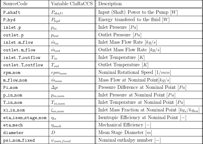
5. Nomenclature
6. Governing Equations
6.1 System Description and General model approach
This component represents a physical turbine model with realistic part load behaviour using the so called stage stacking method according to N. Gasparovic [2]. With this method the behaviour of a single turbine stage is calculated and summed up to achieve the behaviour of a multistage turbine. With few parameters to be set for the point of highest efficiency a typical characteristic can be calculated depending on the actual pressure ratio and drive speed of the machine where the isentropic efficiency depends on the actual flow parameters too. The influence of variable inlet guide vanes is implemented according to [3] and [4] and can be regarded in multiple stages. The deviation of different parameters due to changing variable inlet guide vane positions is regarded by polynomials derived from measurements given in [5]. If wanted a single stage characteristic can be calculated too[6]. The description of this method in detail would exceed this documentation. Please have a look at the given literature to get a closer look into the mentioned stage stacking method.
The model was derived from the CompressorGas_L1_stageStacked component by adapting few equations needed to calculate a turbine behaviour based on the stage stacking method. The approach is described in [4].
Summary
A summary record is available which bundles important component values.
7. Remarks for Usage
- Stationary flow.
- Compressible flow.
- No backflow, no zero flow
9. References
[1] Johannes Brunnemann and Friedrich Gottelt, Kai Wellner, Ala Renz, André Thüring, Volker Röder, Christoph Hasenbein, Christian Schulze, Gerhard Schmitz, Jörg Eiden: "Status of ClaRaCCS: Modelling and Simulation of Coal-Fired Power Plants with CO2 capture", 9th Modelica Conference, Munich, Germany, 2012
[2] N. Gašparovic and D. Stapersma: "Berechnung der Kennfelder mehrstufiger axialer Turbomaschinen", Forschung im Ingenieurswesen, Band 39, 1973
[3] N. Gašparovic and J-W. Kim: "Kennfeldberechnung einstufiger Axialverdichter mit variabler Geometrie", Elektrizitätswirtschaft, Band 5, 1985
[4] H. Göttlich: "Verfahren zur Berechnung der Kennfelder von axialen bzw. radialen, ein oder mehrstufigen thermischen Strömungsmaschinen, auch unter Berücksichtigung des Einflusses von verstellbaren Leitapparaten", Dissertation, Technische Universität Berlin, 1984
[5] B. Eckert and E. Schnell: "Axial- und Radialkompressoren", Springer-Verlag, Berlin, Heidelberg, New York, 1961
[6] N. Gašparovic and H. Göttlich: "Kennfeldberechnung einstufiger Axialverdichter", BWK, Band 37, 1973