
HEXvle2vle L3 2ph CH ntu
Created Monday 10 June 2013
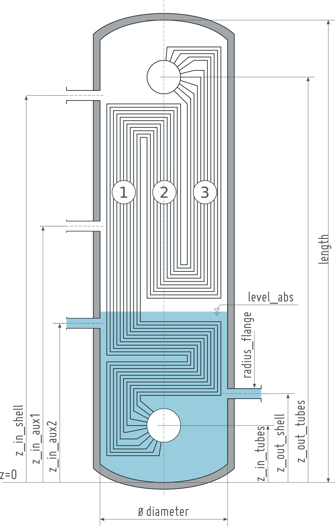
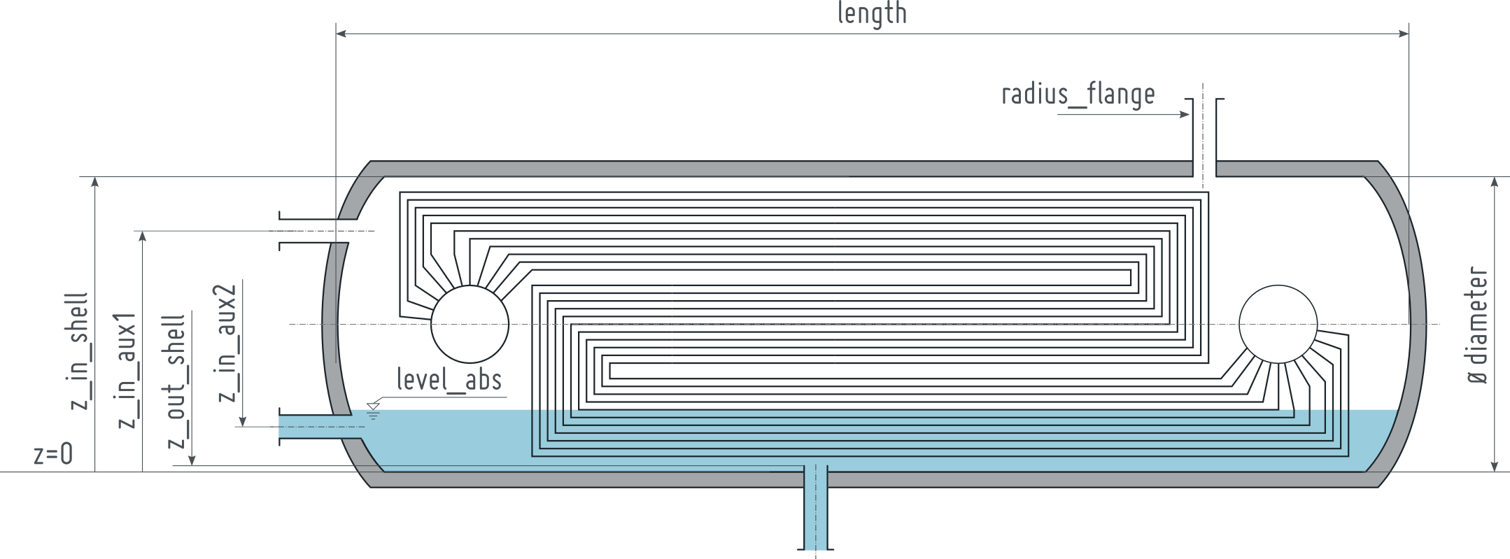
A cylindrical preheater model with non-ideal phase separation at the shell side and NTU-based heat transfer model. A commonly used geometry for high pressure preheaters, i.e. the header-type tube arrangement is assumed.
1. Purpose of Model
This model is well suited to model slow transients of commonly designed high pressure preheaters. If large-scale short-term transients occur, e.g. as can be found during start-up the model might give imprecise results since the basic assumptions of the NTU approach (applied for calculation of heat resistance) can be violated.
2. Level of Detail, Physical Effects Considered and Physical Insight
2.1 Level of Detail
Referring to Brunnemann et al. [1], this model refers to the level of detail L3 because the system is modelled with the use of balance equations applied to three different zones of the component: liquid condensate at tube side, vapour and liquid volume at shell side.
2.2 Physical Effects Considered
- dynamic conservation of energy (neglecting kinetic energy terms) in condensating and cooling flows
- dynamic conservation of mass (neglecting kinetic energy terms) in condensating and cooling flows
- taking static pressure differences due to friction losses and geostatic into account
- calculation of heat transfer resistance between the two flows is calculated according to a three-zonal NTU model
- heat transfer from condensing steam to cooling water, losses to the ambience is neglected
- pressure losses due to friction at condensating and cooling flows
- phase separation at the condensating side, discrete balancing of liquid and vapour zone
2.3 Level of Insight
Heat Transfer
shell side
- Basics:ControlVolumes:Fundamentals:HeatTransport:VLE HT:Constant L3 ypsDependent : a constant heat transfer coefficient in liquid and vapour zone
tube side:
- Basics:ControlVolumes:Fundamentals:HeatTransport:Generic HT:Constant L2 : a constant heat transfer coefficient
- Basics:ControlVolumes:Fundamentals:HeatTransport:Generic HT:IdealHeatTransfer L2 : ideal heat transfer, i.e. kc is infinite (see also the remarks for usage)
- Basics:ControlVolumes:Fundamentals:HeatTransport:Generic HT:CharLine L2 : heat transfer coefficient calculated from nominal value and a mass flow dependenet correction
- Basics:ControlVolumes:Fundamentals:HeatTransport:VLE HT:NusseltPipe1ph L2 :heat transfer
Pressure Loss
shell side
- Basics:ControlVolumes:Fundamentals:PressureLoss:Generic PL:NoFriction L3 : friction free flow between inlet and outlet
- Basics:ControlVolumes:Fundamentals:PressureLoss:Generic PL:LinearParallelZones L3 : Linear pressure loss based on nominal values, different zones are seen in parallel, pressure loss is located at flanges
- Basics:ControlVolumes:Fundamentals:PressureLoss:Generic PL:LinearSerialZones L3 : Linear pressure loss based on nominal values, different zones are seen in series
- Basics:ControlVolumes:Fundamentals:PressureLoss:Generic PL:QuadraticParallelZones L3 : Quadratic pressure loss based on nominal values, different zones are seen in parallel, pressure loss is located at flanges
tubes side
- Basics:ControlVolumes:Fundamentals:PressureLoss:Generic PL:NoFriction L2 : friction free flow between inlet and outlet
- Basics:ControlVolumes:Fundamentals:PressureLoss:Generic PL:LinearPressureLoss L2 : Linear pressure loss based on nominal values, different zones are seen in parallel, pressure loss is located at flanges
- Basics:ControlVolumes:Fundamentals:PressureLoss:Generic PL:QuadraticNominalPoint L2 : Quadratic pressure loss based on nominal values, different zones are seen in parallel, pressure loss is located at flanges, density independent
- Basics:ControlVolumes:Fundamentals:PressureLoss:VLE PL:PressureLossCoefficient L2 : Density dependent pressure loss based on zeta value
- Basics:ControlVolumes:Fundamentals:PressureLoss:VLE PL:QuadraticNominalPoint L2 : Density dependent, quadratic pressure loss based on nominal values
Phase Separation
shell side
Basics:ControlVolumes:Fundamentals:SpatialDistributionAspects:RealSeparated : non-ideal phase separation, state at ports depend on filling level and state of the distinct zones.
tube side:
Basics:ControlVolumes:Fundamentals:SpatialDistributionAspects:IdeallyStirred : ideally mixed phases
3. Limits of Validity
- only small transients are allowed due to application of NTU-based wall model.
- no flow reversal is supported
- mass flows from shell side connectors 2 and 3 shall be small compared to mass flow through connector 1
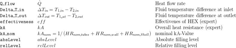
4. Interfaces
5. Nomenclature
6. Governing Equations
6.1 System Description and General model approach
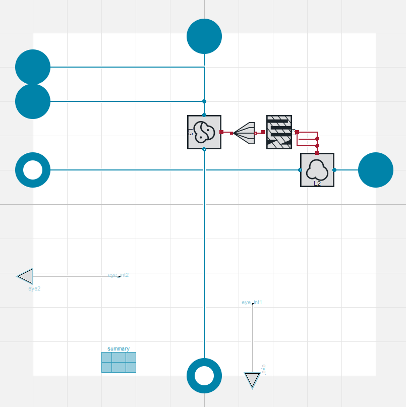
This model is composed by instantiation of the following classes:
- Basics:ControlVolumes:FluidVolumes:VolumeVLE L2 volume of the condensate volume in the pipes
- Basics:ControlVolumes:FluidVolumes:VolumeVLE L3 TwoZonesNPort : volume of the shell side with condensing steam
- Basics:ControlVolumes:SolidVolumes:NTU L3 to model the heat transfer resistance and the temperature distribution in the heat exchanger
6.2 General Model Equations
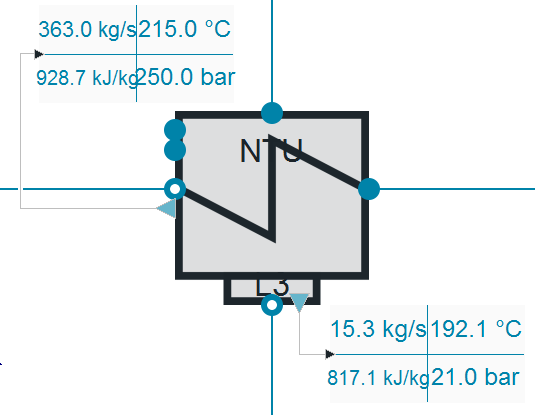
Summary
A record summarising the most important variables is provided. Please be aware of the boolean showExpertSummary in the parameter dialog tab "Summary and Visualisation". Setting this parameter to true will give you more detailed information on the components behaviour. The summary consists of the outline:
and the summaries of the class instances named in section 6.1
7. Remarks for Usage
- As a more robust but less accurate alternative consider Components:HeatExchangers:HEXvle2vle L3 2ph CH simple.
- Some control concepts need a level dependent behaviour of the heat transfer, e.g. if tube outlet temperature is influenced by control valve which lies downstream the shell outlet. In that case Components:HeatExchangers:HEXvle2vle L3 2ph CH simple has to be considered as the filling level has no influence on the NTU-based heat transfer calculation.
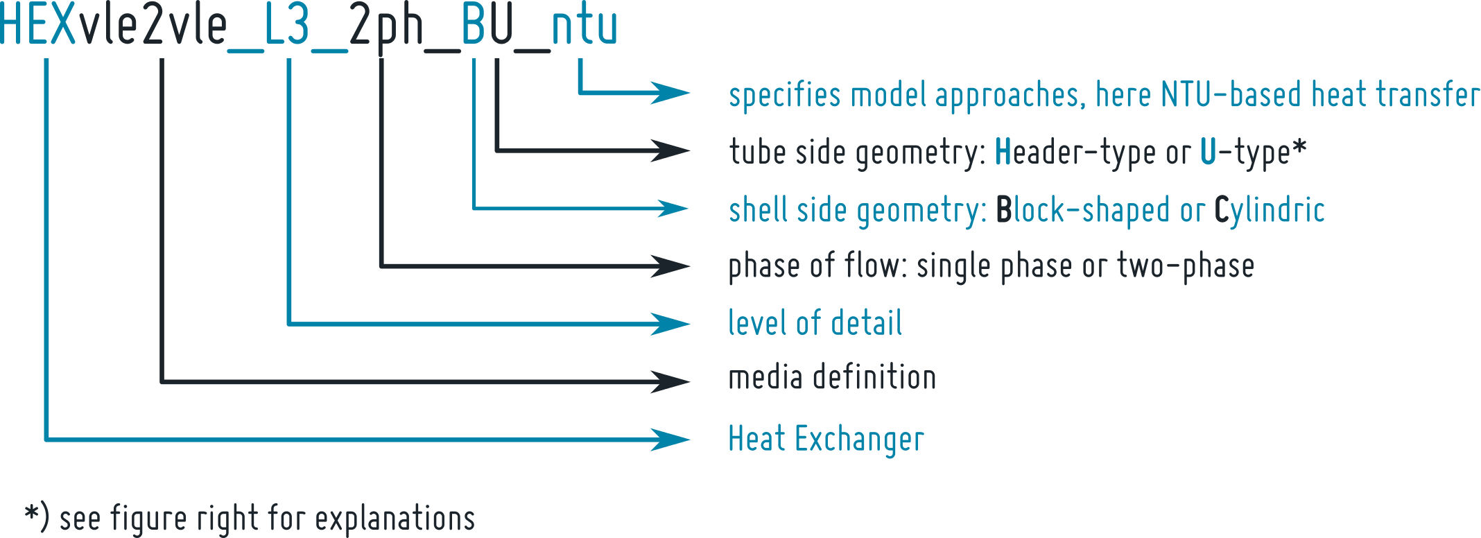
7.1 Naming
The naming of heat exchangers in this package follows some specific form that is defined as follows:

7.2 Heat Transfer Modelling
In most cases the heat transfer from one fluid to the other will be dominated by the heat transfer at one of fluid boundary layers. In that cases the heat transfer coefficient α at this side will be considerably smaller than on the other side. From a numerical point of view it is disadvantageous to have very high (close to infinite) heat transfer coefficients on either sides. If you want to take nearly ideal heat transfer at one of the sides into account please consider the corresponding replaceable model instead of defining arbitrary large heat transfer coefficients in the model.
7.3 Initialisation and Numerical Robustness
During first testing of NTU-based heat exchanger models it became apparent that the initialisation might be difficult. For the sake of numerical robustness of the model two PI controllers are internally used to adjust the area fraction of the different zones in the NTU wall. If you encounter problems during initialisation you might want to adjust the initialisation conditions of these PI blocks by right clicking on the HEX and choose "show component".
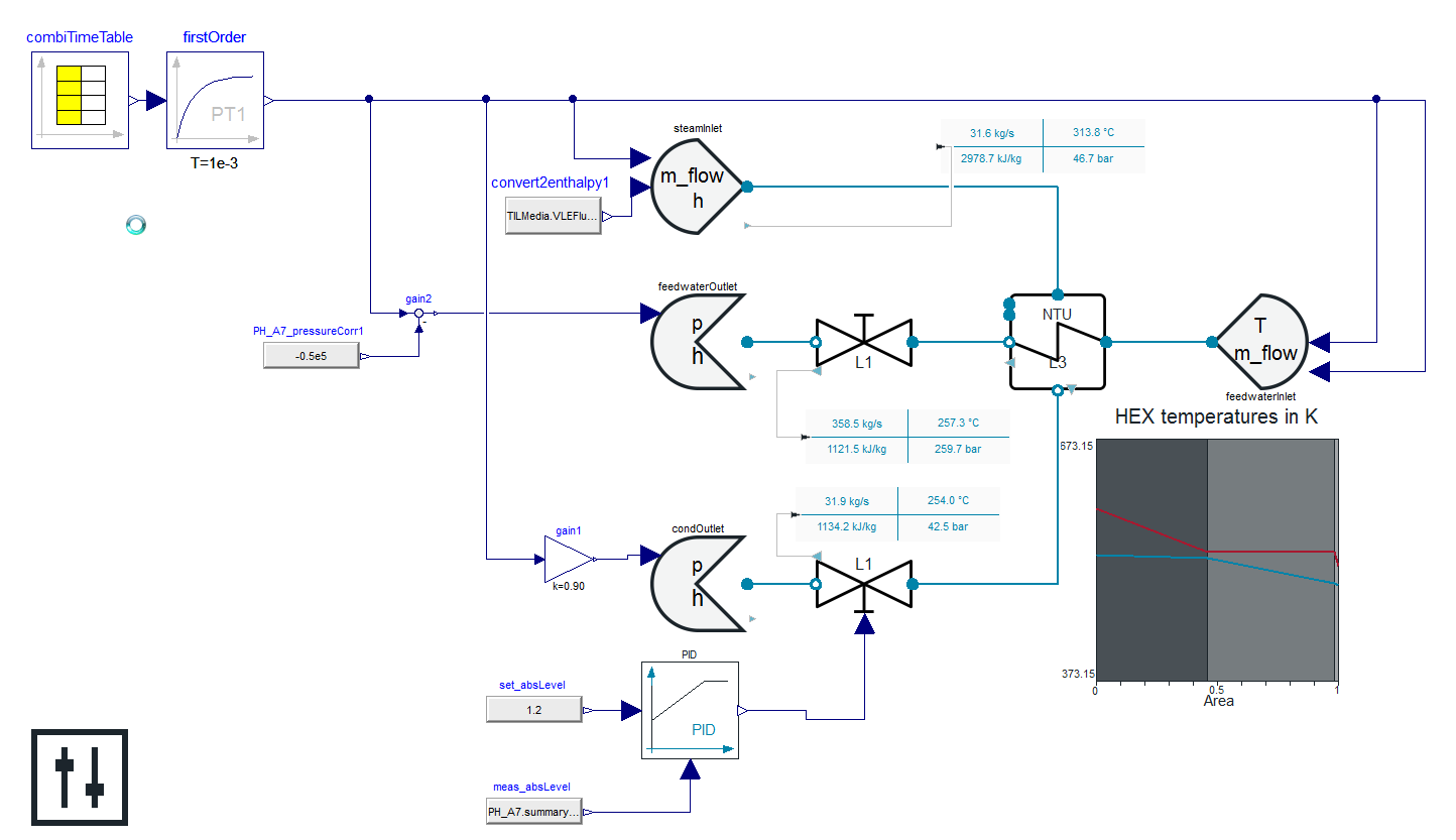
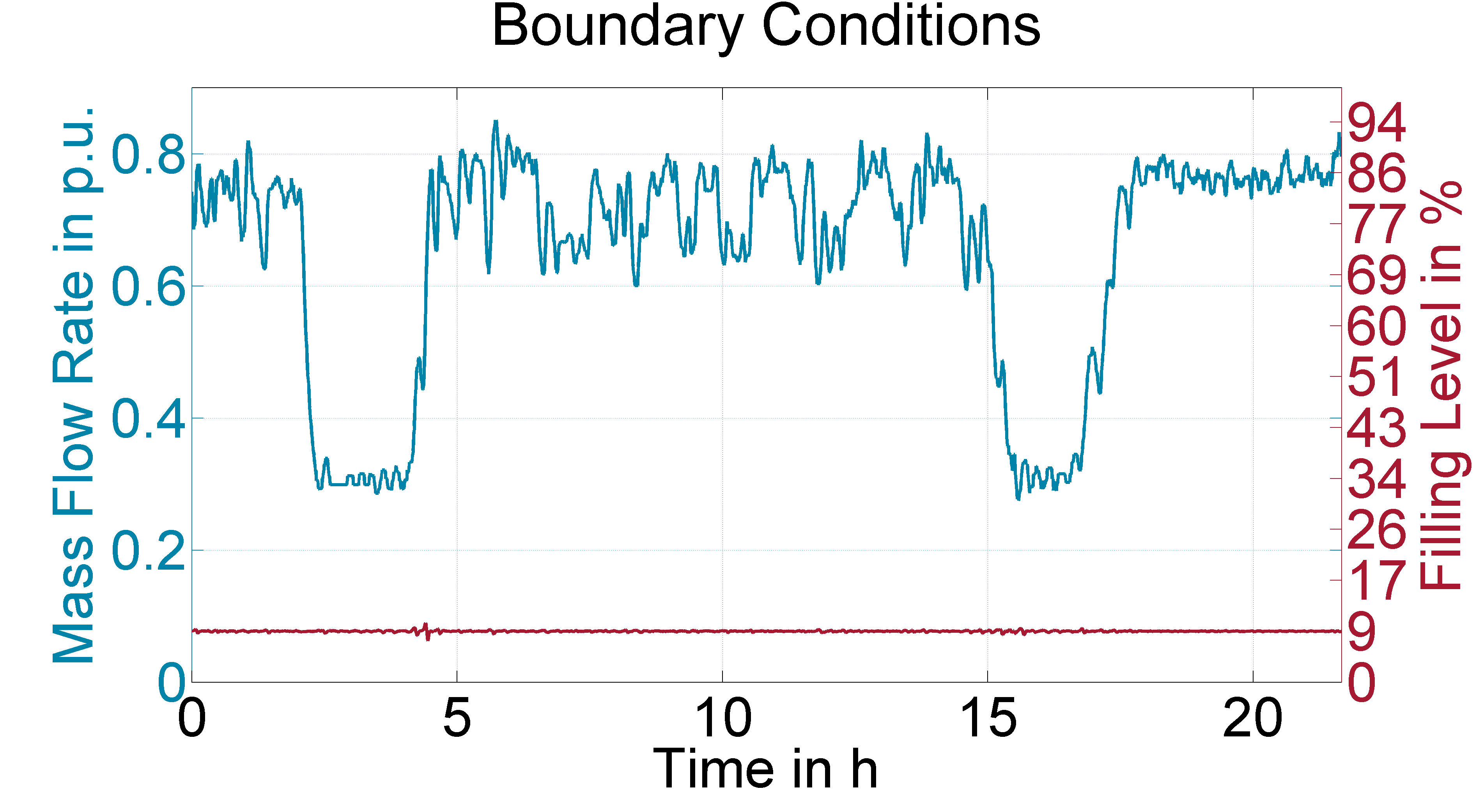
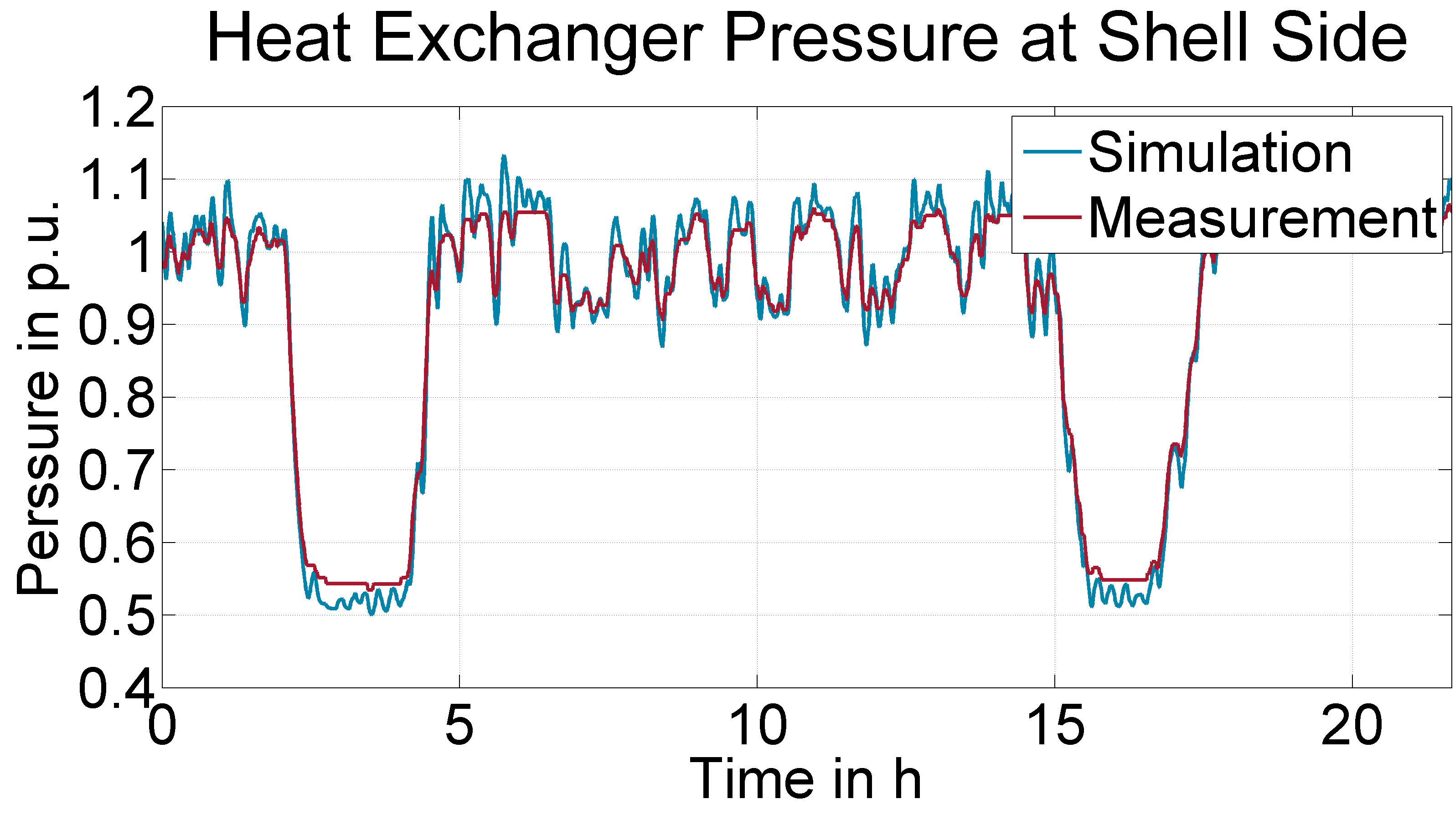
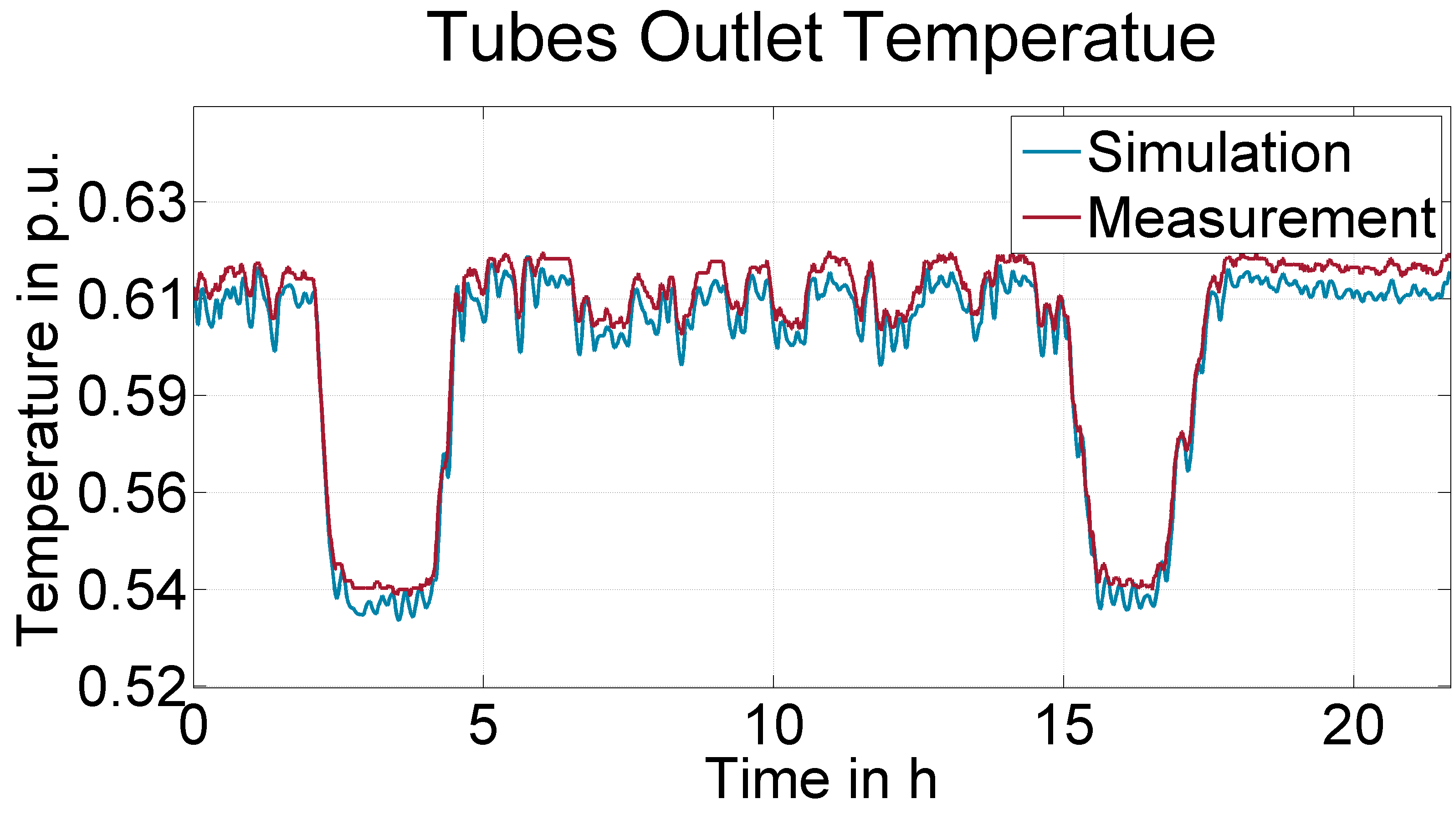
8. Validation
The heat exchanger is validated using measurement data from a German 550 MW block. The scenario comprises a business as usual operation of a high pressure preheater featuring four large load steps.
9. References
[1] Johannes Brunnemann and Friedrich Gottelt, Kai Wellner, Ala Renz, André Thüring, Volker Röder, Christoph Hasenbein, Christian Schulze, Gerhard Schmitz, Jörg Eiden: "Status of ClaRaCCS: Modelling and Simulation of Coal-Fired Power Plants with CO2 capture", 9th Modelica Conference, Munich, Germany, 2012
10. Authorship and Copyright Statement for original (initial) Contribution
Author:
DYNCAP/DYNSTART development team, Copyright 2011 - 2025.
Remarks:
This component was developed during DYNCAP/DYNSTART projects.
Acknowledgements:
ClaRa originated from the collaborative research projects DYNCAP and DYNSTART. Both research projects were supported by the German Federal Ministry for Economic Affairs and Energy (FKZ 03ET2009 and FKZ 03ET7060).
CLA:
The author(s) have agreed to ClaRa CLA, version 1.0. See https://claralib.com/pdf/CLA.pdf
By agreeing to ClaRa CLA, version 1.0 the author has granted the ClaRa development team a permanent right to use and modify his initial contribution as well as to publish it or its modified versions under the 3-clause BSD License.
11. Version History
- 2013 - v 0.1 - initial implementation - A.Renz, F.Gottelt, XRG Simulation
- 07.03.2016 - v 1.1.0 - Corrected A_front corrected for parameterisations with flowOrientation not equal to geometrical orientation
- Temperatures at shell side for NTU-based heat transfer calculation are now calculated with inlet pressure instead of outlet pressure
- 28.04.2016 -v 1.1.1 - offer option to set position of liquid pressure state either at the liquid surface of at the vertical middle of the zone
- 08.01.2019 -v 1.4.0 - added kA-value to summary
- bugfixed underlying NTU wall model - Annika Kuhlmann, Timm Hoppe, XRG Simulation GmbH