
Hopper L2
Created Tuesday 18 June 2013
A 0d-hopper model with nonstationary mass and energy balance regarding radiative heat transfer with the connected furnace model and heat transfer to the boiler casing walls.
1. Purpose of Model
This model is well suited to model the hopper area of a boiler. In combination with Burner and FlameRoom models a 1-dimensional boiler model could be achieved which is discretised in flow direction. Radiative heat transfer to the connected furnace model and boiler casing walls can be calculated using replaceable models.
2. Level of Detail, Physical Effects Considered and Physical Insight
2.1 Level of Detail
Referring to Brunnemann et al. [1], this model refers to the level of detail L2.
2.2 Physical Effects Considered
- this model uses TIL-Media
- nonstationary conservation of energy (neglecting kinetic energy terms)
- nonstationary conservation of mass
- calculation of radiative heat transfer to the connected furnace model
- calculation of radiative heat transfer to boiler casing walls
- constant pressure (until now no pressure losses are implemented)
2.3 Level of Insight
Heat Transfer
top (radiation to neighbored furnace volumes)
- RadiantHeat_GasToGas: calculation of radiant heat transfer between furnace models with constant emissivity and absorbance values
- RadiantHeat_GasToGas_epsilon_calc: calculation of radiant heat transfer between furnace models with constant or calculated emissivity and absorbance values (temperature dependent calculation of gas and particle emissivities)
wall (radiation or convection to boiler casing walls) :
- RadiantHeat_GasToWall: calculation of radiant heat transfer between furnace model and boiler casing walls with constant emissivity and absorbance values
- RadiantHeat_GasToWall_epsilon_calc: calculation of radiant heat transfer between furnace model and boiler casing walls with constant or calculated emissivity and absorbance values (temperature dependent calculation of gas and particle emissivities)
- ConvectiveHeat_GasToWall: calculation of convective heat transfer to boiler casing walls
Pressure Loss
No pressure losses are considered.
3. Limits of Validity
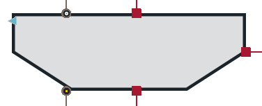
4. Interfaces
4.1 Physical Connectors
Basics:Interfaces:FuelSlagFlueGas inlet inlet
Basics:Interfaces:FuelSlagFlueGas outlet outlet
Basics:Interfaces:HeatPort a heat_top
Basics:Interfaces:HeatPort a heat_bottom
Basics:Interfaces:HeatPort a heat_wall
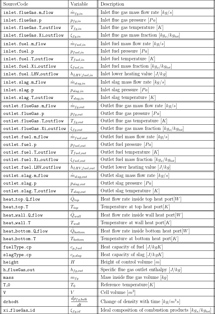
5. Nomenclature
6. Governing Equations
6.1 System Description and General model approach
This model is used to build up furnace models with 1-dimensional discretisation and is used together with other models of the furnace package.
This model supports an nonstationary energy and mass balance (only thermal expansion considered) for the flue gas while no combustion of fuel is considered in this component.
The component exchanges heat flows with up- and downstream models (heat_top and heat_bottom port) as well as the surrounding walls (heat_wall) which are calculated with replaceable models for heat transfer correlations. If radiative heat transfer correlations are used inside a 1-dimensional discretised (sequential model arrangement) furnace, radiative heat flows are exchanged between the directly connected models (via heat ports top and bottom) and the surrounding walls (heat port wall). The calculation is performed with view factors which are calculated inside the heat transfer correlations. The following sketch shows the modelling principle for radiative heat transfer between the sequential arranged volumes and the calculation formula for the view factor. The amount of emitted radiation is calculated for a three dimensional volume, but the radiative heat flow between the models is assumed to be exchanged between two flat surfaces with the size of the furnace cross sectional area.
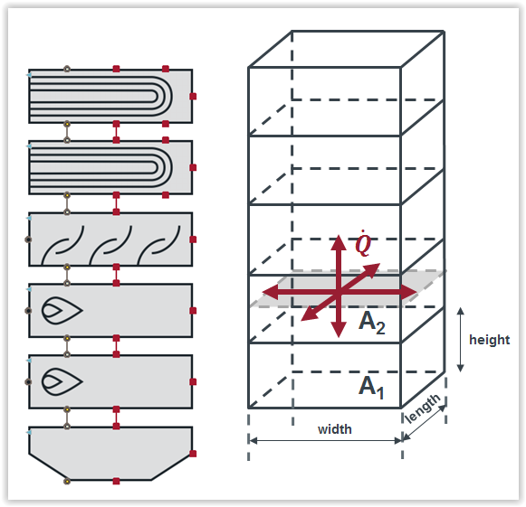
In case of heat transfer to the surrounding walls the view factor is calculated in a different way which is not shown here.
6.2 General Model Equations
This model only considers a nonstationary energy and mass balance for the flue gas with no chemical reaction taking place.
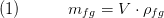
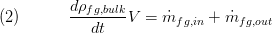
The overall gas mass inside the volume is calculated with the mean value of the the inflowing gas mixture and the bulk density as follows:
The solid particles of fuel (here mainly coal) are neglected.
The nonstationary mass balance for the flue gas is calculated as follows. Thermal expansion is considered while the pressure has no influence. Except the ash fraction, the amount of burned fuel is added to the flue gas:
with

The mass balances of slag and fuel are modeled stationary and are not effected from the thermal expansion of the flue gas:


The flue gas enthalpy inside the control volume, which is used to calculate the outlet temperature with a media object, is calculated with the following energy balance:
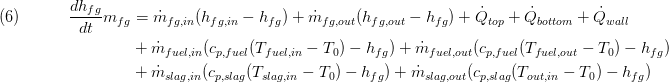
The resulting flue gas composition inside the hopper volume is calculated as follows:

Summary
A summary record is available which bundles important component values.
7. Remarks for Usage
8. Validation
The adiabatic outlet temperature of this model has been validated with Ebsilon calculations at identical boundary conditions.
9. References
[1] Johannes Brunnemann and Friedrich Gottelt, Kai Wellner, Ala Renz, André Thüring, Volker Röder, Christoph Hasenbein, Christian Schulze, Gerhard Schmitz, Jörg Eiden: "Status of ClaRaCCS: Modelling and Simulation of Coal-Fired Power Plants with CO2 capture", 9th Modelica Conference, Munich, Germany, 2012
10. Authorship and Copyright Statement for original (initial) Contribution
Author:
DYNCAP/DYNSTART development team, Copyright 2011 - 2025.
Remarks:
This component was developed during DYNCAP/DYNSTART projects.
Acknowledgements:
ClaRa originated from the collaborative research projects DYNCAP and DYNSTART. Both research projects were supported by the German Federal Ministry for Economic Affairs and Energy (FKZ 03ET2009 and FKZ 03ET7060).
CLA:
The author(s) have agreed to ClaRa CLA, version 1.0. See https://claralib.com/pdf/CLA.pdf
By agreeing to ClaRa CLA, version 1.0 the author has granted the ClaRa development team a permanent right to use and modify his initial contribution as well as to publish it or its modified versions under the 3-clause BSD License.
11. Version History
- 2013 - v 0.1 - initial implementation - L. Nielsen, A. Thüring, TLK-Thermo GmbH
- 26.03.2019 - chattering countermeasures applied (noEvents)
Backlinks: ClaRa:Components:Furnace:Burner:Burner L2 Dynamic ClaRa:Components:Furnace:Burner:Burner L2 Dynamic fuelDrying ClaRa:Components:Furnace:Burner:Burner L2 Static ClaRa:Components:Furnace:FlameRoom:FlameRoomAdditionalAir L2 Dynamic ClaRa:Components:Furnace:FlameRoom:FlameRoomAdditionalAir L2 Static ClaRa:Components:Furnace:FlameRoom:FlameRoomWithTubeBundle L2 Dynamic ClaRa:Components:Furnace:FlameRoom:FlameRoomWithTubeBundle L2 Static ClaRa:Components:Furnace:FlameRoom:FlameRoom L2 Dynamic ClaRa:Components:Furnace:FlameRoom:FlameRoom L2 Static